Setting Up Your Builders’ Level And Using It Effectively On A Project.
Words: Steven Fechino
Steven Fechino
Setting up your builders’ level
As a mason, you always need to hit the mark, reach a certain elevation, or top out at the correct level. We always seem to top out at another trades bottom. How we decide where we hit the mark is usually by taking someone else’s benchmark or control point and working in the proper direction. Once we know where we are going to build to, we can then adjust our coursing so we can supply the customer with a good-looking wall with consistent bed joints.
In the case where we are laying out our work, we sometimes use a builder’s level. This article is very basic. I have simplified it so it is usable in the field immediately after reading this article. Builders’ levels come in a variety of qualities but overall are a very simple tool that can be used effectively. I am going to begin by showing how to check the level for accuracy. It is a simple two-step process that can be done in a matter of minutes and can eliminate the worries of an unlevel layout.
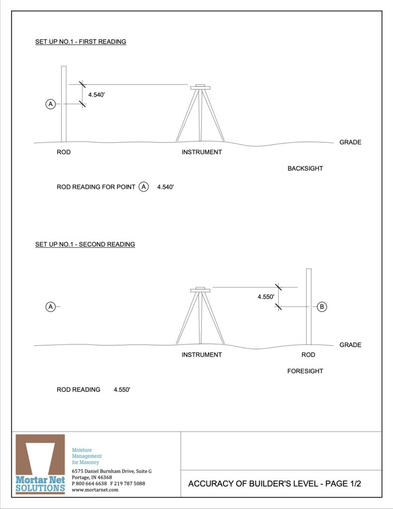
You begin by setting up between two points approximately 30 feet in each direction. On the left, you will have point A and on the right, you will have point B. Using the height of the instrument, measure down to the points A and B, and record the measurements. Next, set up the instrument about 10 feet away from point A. Take a second reading towards point A, (we will call this point C) and toward point B, (we will call this point D).
Here is the simple math: Point A minus point C should equal Point B minus Point D. If you have more than a slight difference, then you should consider having your instrument calibrated.
Stadia Measurements:
Stadia just means a unit of length. If you need to shoot distances with the builders’ level, this is a simple process as well. When you look through the eyepiece of the instrument you will see three horizontal lines, upper-middle, and lower.
The formula is D (distance) = R (rod intercept which is the upper line measurement -lower line measurement) X 100 (this is a factor designated by instrument manufacturer and can vary based on manufacturer preference) + 1.
This is not used typically in day to day operations unless you need to cover terrain that is obstructed or on a project where the layout person is unavailable. The main purpose of this explanation was to let you know what the different horizontal lines represent when looking through the eyepiece of the instrument.
Differential Leveling
Differential leveling is very common when doing a layout with non-digital instruments. When shooting different points using the instrument a Backsight is a plus (looking to the point on the left) and a Foresight is a minus (when you rotate to look at the point on the right). The datum is typically sea level and can usually be considered at 0.00 elevation. You need to know what the datum is to compute the instrument height.
Instrument height will be taken from a known control point or a benchmark and either added to or subtracted from the rod reading viewed from the centerline of the eyepiece of the instrument. So, in our example, Elevation control point A is at 320.00 Feet. Our rod reading using the centerline was 2.40 feet higher than the control point A. That made out instrument height (320.00 feet plus 2.40 feet = 322.40 feet). Now we have the instrument height it gets easy to follow. Now, any measurement we shoot will be calculated from the instrument height and will be immediately known.
Say we shoot another point of the building where we need to turn a corner and begin out walls, but in this case, the footer has stepped several times and looks a little rough. Take a reading to the corner at the top of the footing on the rod and minus it from the height of the instrument. 322.40 feet (height of instrument)-10.30 feet (rod reading to top of footing) = 312.10 feet. That is the elevation at the top of the footing.
Lastly, the measurements are in feet and tenths of an inch, which is engineering scale (engineers do this on civil drawings). You can convert the tenths to inches easily by dividing SI inches by 12 inches per foot and you will be ready to go. Here is a common one we use. 8 inches / 12 inches per foot =0.67 feet. This works for every increment of inches.