Photos: David BiggsThis issue’s questions come from an Engineer and an Architect. What questions do you have? Send them to
info@masonrymagazine.com, attention Technical Talk.
Q. An Engineer asked when the reinforcement for the masonry diaphragm chords must be continuous through the corners. Where is this discussed in the building code?A. This is an interesting question and one not commonly discussed. Masonry diaphragm chords are reinforced elements generally installed as bond beams at the tops of walls. They serve multiple purposes as diaphragm chords, provide a direct connection to the diaphragm, and stiffen the wall to support the bearing loads.
Overall, the building code expects every design to achieve the necessary strength, stiffness, and stability to resist the expected loads. But there are no prescriptive requirements specific to continuity of masonry diaphragm chords.
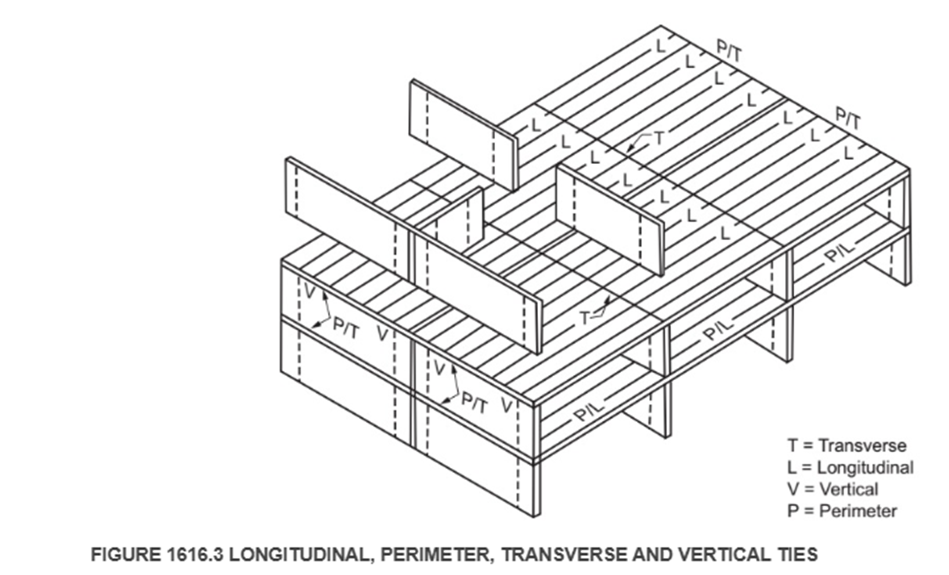
One criterion that specifies reinforcement continuity at corners is IBC Section 1616.3.2.3 Perimeter Ties. But these ties are only mandatory for high-rise buildings (over 75 feet tall for loadbearing masonry) that are assigned to Risk Category III or IV.
Figure 1616.3 is taken from the IBC regarding structural integrity. The perimeter ties are shown as P/T and P/L. Although not specifically stated, continuity implie that the ties are continuous through the corners. The perimeter ties can be included within the perimeter walls thereby also serving as masonry diaphragm chords.
While these are prescriptive requirements, engineers can include similar criteria in their projects deemed of significant importance such as concerns over progressive collapse, high wind designs, and other designs.
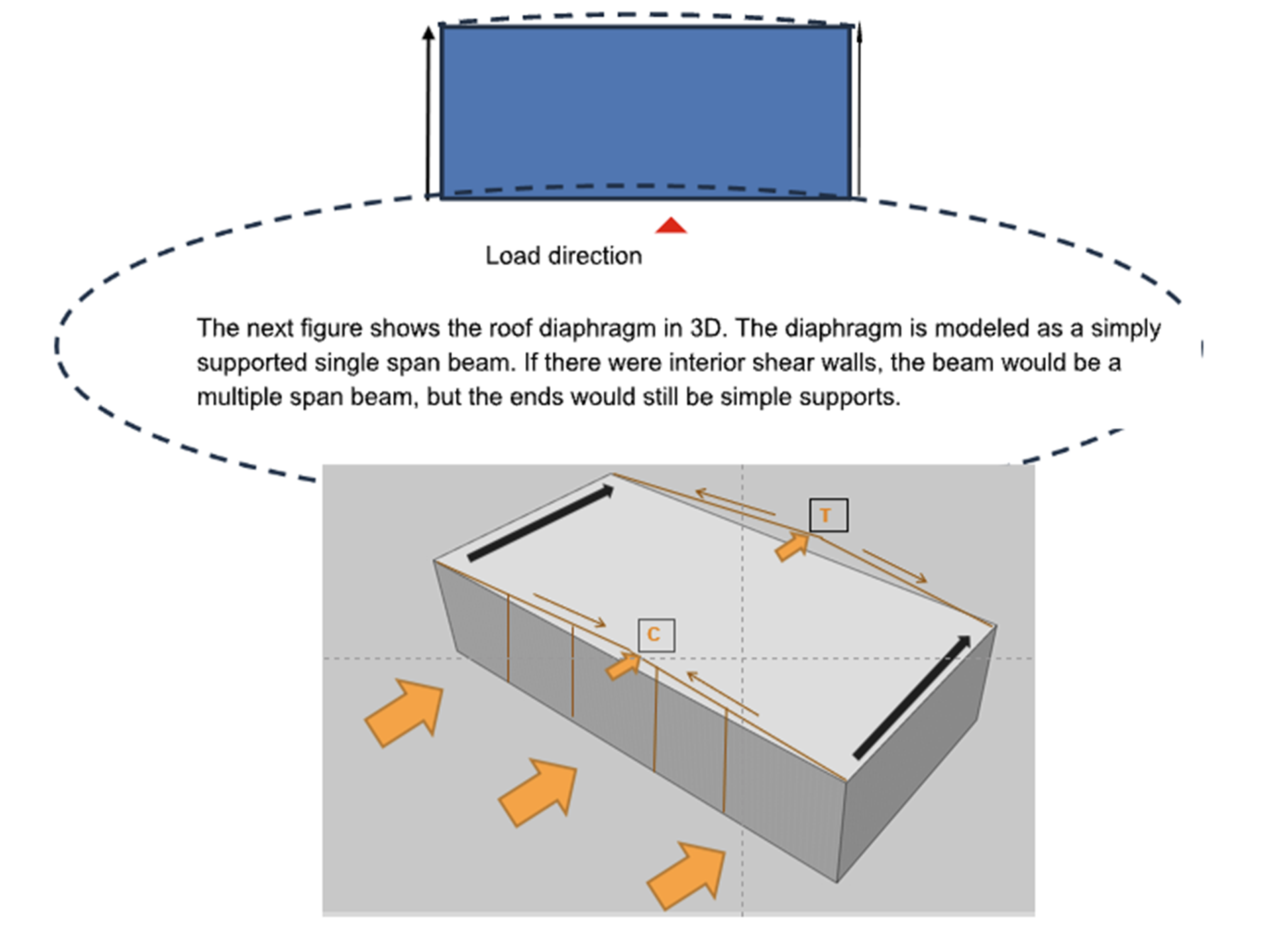
Masonry diaphragms are flat beams shown graphically in the next plan figure. The +diaphragm shows the shear loading going into the shear walls while the flexural stresses going to the masonry diaphragm chords. The forces could also be reversed, and similar conditions would exist if the load were applied to the side walls.
So, the question of continuity at the corners exists. For this, we consider two TMS 402 sections.
a. TMS 402-16, Section 6.1.9.1.3 states “ Reinforcement shall extend beyond the point at which it is no longer required to resist flexure for a distance equal to the effective depth of the member or 12db, whichever is greater, except at supports of simple spans and at the free ends of cantilevers.” So, by modeling the ends of the diaphragm as a simple support, the reinforcement does not have to be continuous around the corner by this section.
b. TMS 402-16, Section 6.1.9.2 states “Development of positive moment reinforcement – When a wall or other flexural member is part of the lateral-force-resisting system, at least 25 percent of the positive moment reinforcement shall extend into the support and be anchored to develop the yield strength of the reinforcement in tension.” Thus, since the diaphragm is part of the lateral-force-resisting system, 25 percent of the diaphragm bars need to extend into the support (the corner) and anchored.
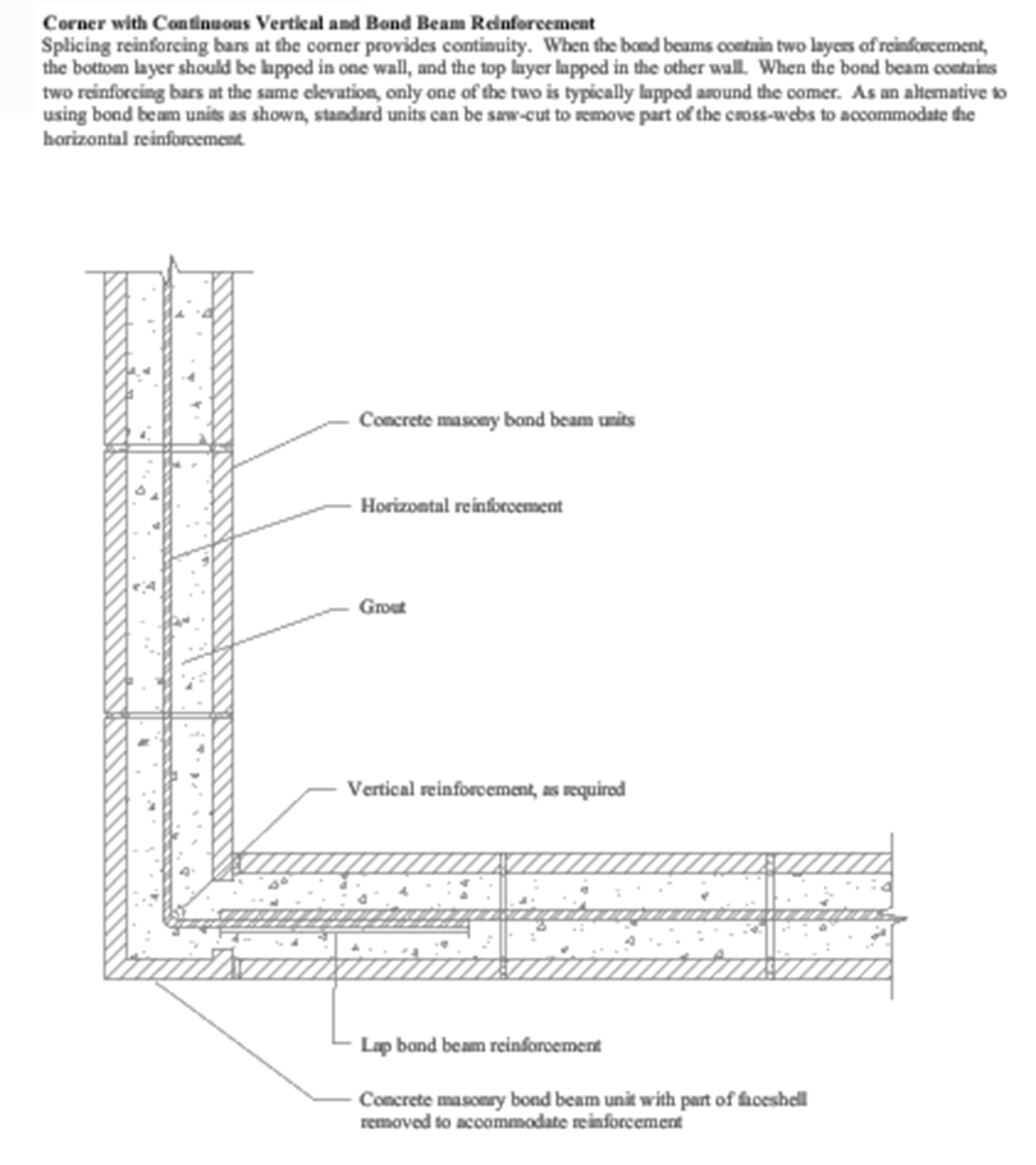
Typically, bond beams have two horizontal reinforcement bars. Therefore, a practical detail would be to extend one of the bars around the corner and develop it.
Figure 7D.1 of the NCMA (now CMHA) Annotated Design and Construction Details for Concrete Masonry provides detailing information for continuity at corners. While it does not discuss the code basis for the detail, it does propose that one of every two bars be continuous around a corner.
 Summary:
- There is a code basis for requiring continuity of reinforcement at corners for masonry diaphragm chords because they are part of the lateral-force-resisting system.
- If the diaphragm chords are not masonry (such as steel angles or other framing), the bond beam reinforcement at the top of the wall need not be continuous around corners.
- If there are masonry diaphragms the chords must be continuous around the corner if the shear wall is continuous around the corner also.
Q. An Architect has noted a discrepancy between the IBC and TMS 402-22 for anchoring stone. IBC Section 1404.7 Stone Veneer requires a minimum of 1-inch grout between the stone and the backing, while TMS 402 Chapter 13 does not require any grout. Can you explain?A. This is a confusing issue and is certainly open to interpretation. Follow me on this:
a. IBC Section 1403.4 Masonry directs us to Chapter 21 also.
b. IBC Section 2101.2 Design Methods refers us to TMS 402. This gives us a path to the TMS veneer criteria.
c. IBC Section 2101.2.1 Masonry Veneer refers us back to IBC Chapter 14.
d. IBC Section 2103.1 Masonry Units refers us to TMS 602 Article 2.3, which specifies the ASTM standards for various dimension stones.
e. Now we go back to IBC Section 1404.7 Stone Veneer, where we now know we are discussing dimension stone. This section provides prescriptive criteria for anchoring dimension stone veneers up to 10-inches thick. This is where the 1-inch (minimum) cement grout is to be used as a backer for the stone in addition to the prescriptive anchor requirements.
f. But looking at TMS 402, Chapter 13, Table CC-13.1.1 indicates that when designing with TMS 402, the Engineered Method must be used and not the Prescriptive Method. The Engineered Method of Section 13.2.3 requires the designer to account for the strength and stiffness of the ties; there is no mention of requiring grout behind the stone. It is left to the designer to determine whether grouting is needed.
So, we have two different options, the IBC method and the TMS 402 method. Some say the IBC method must be followed. Following the path I have outlined, others say both are acceptable. You could discuss this with the code official before planning a design, but you might have to bring along the coffee!
Summary:
- The IBC does not specifically state that it offers a prescriptive method for anchoring thick stone veneers that avoids the TMS 402 Engineered method.
- Hopefully, this can be addressed in a future code edition.
Thank you again for following this column. Remember, by bonding, we get stronger! Keep the questions coming. Send them and your comments to info@masonrymagazine.com, with attention to Technical Talk. If you have missed any of the previous articles, you can find them online for Technical Talk, Bonding with Masonry at Masonry Design magazine.
______
David is a PE, SE with Biggs Consulting Engineering, Saratoga Springs, NY, USA (www.biggsconsulting.net), and an Honorary Associate Professor with the University of Auckland, NZ. He specializes in masonry design, historic preservation, forensic evaluations, and masonry product development.
Keywords for this issue: masonry, diaphragm chords, corners, lateral-force-resisting system, stone veneer anchorage