Photos: David Biggs, IMI 3D Warehouse, Pavement Services – HoustonThis issue’s questions come from an Architect and an Engineer. What questions do you have? Send them to info@masonrymagazine.com, attention Technical Talk.
- Q. An Architect stated that we often talk about putting movement joints in the CMU walls and veneers, but is it necessary to place movement joints in the foundation wall below an anchored clay brick veneer?
- A. This is a very good question! I am unaware that TMS 402 (the code masonry standard) specifically addresses this topic, so I will give you my interpretation.
Practically, we would prefer no foundation joints below grade. Sealing them and maintaining them is a maintenance nightmare. If a moisture or waterproofing barrier is used, bridging the wall joints is again problematic. Also, since much of the foundation (concrete or reinforced CMU) movement is shrinkage-related, the moist ground will moderate the long-term shrinkage.
For this discussion, we’ll only address grade walls, not basement walls or a grade-beam system. Then, let’s separate concrete grade walls from reinforced masonry grade walls.
For concrete, ACI (American Concrete Institute) documents 318 and PRC-224-01 address shrinkage cracking and joints in general. They discuss contraction joints and construction joints. Much like CMU control joints, contraction joints are intended to control shrinkage in concrete walls in exposed applications. Construction joints are more for the convenience of the construction sequence.
For concrete grade walls, the thought is that the walls are reinforced and little exposed, so that contraction joints don’t seem to be needed. Often, just the top of the foundation wall is exposed. The IBC does not specify a minimum value for exposure; the residential code (IRC) gives 4 inches (minimum). Preferably, the top of the wall is designed with sufficient reinforcement to minimize shrinkage cracking.
If construction joints are used, the recommendation is that the joint placement closely align with a masonry veneer movement joint above. We say closely align and not exactly align because the flashing material used below masonry walls will allow some slip
(see Figure 1, which shows an IMI detail of the base of the wall). The brick ledge places the floor line above grade, and the flashing allows some slip for brick expansion. The concrete foundation can be reinforced to minimize shrinkage potential for the exposed surface.
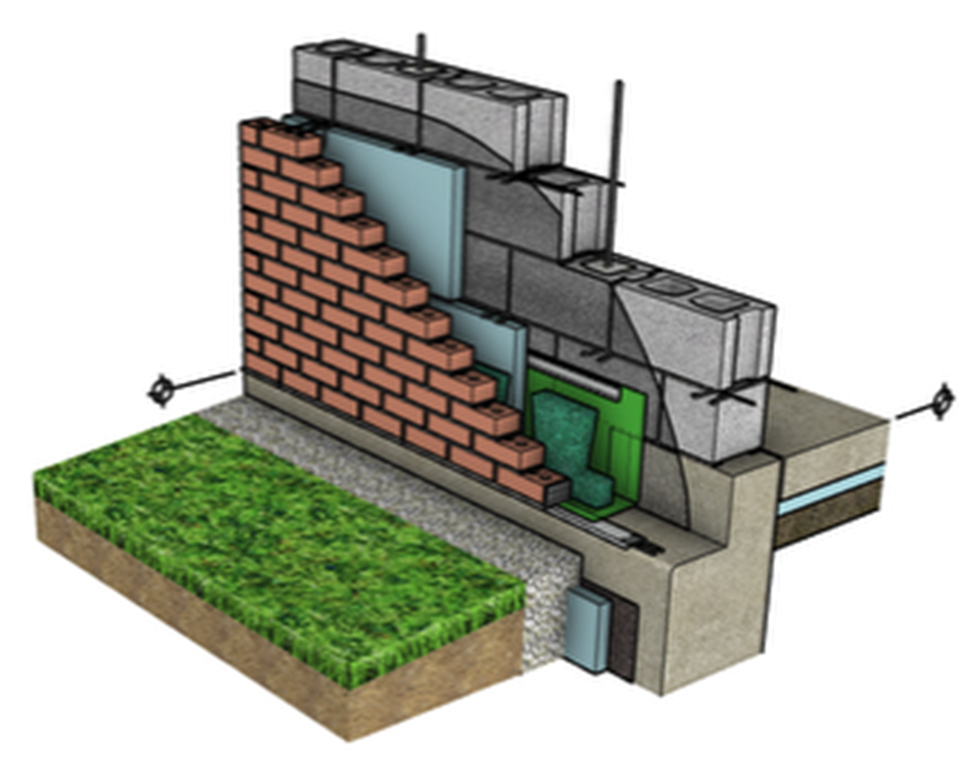 Figure 1 – Base of Wall Detail – Concrete foundation (courtesy of IMI 3D Warehouse)
For reinforced CMU foundation walls, the logic is much the same. Figure 2 shows a CMU foundation. Again, the flashing aids in allowing some slip between the brick and CMU support. The CMU units directly below the brick veneer are shown solid grouted and unreinforced in this detail. I suggest reinforcing these with a bond beam and including movement joints aligned with the brick above.
The reinforced CMU grade wall is shown unexposed and coated with a moisture membrane. The membrane could be optional. No movement joints are needed if bond beam reinforcement is provided per CMHA Technical Note CMU-TEC-009-25, Crack Control Strategies for Concrete Masonry Construction. The note offers an option for using bond beam reinforcement to eliminate movement joints. The structural walls above-grade would have movement joints or not, based on the design.
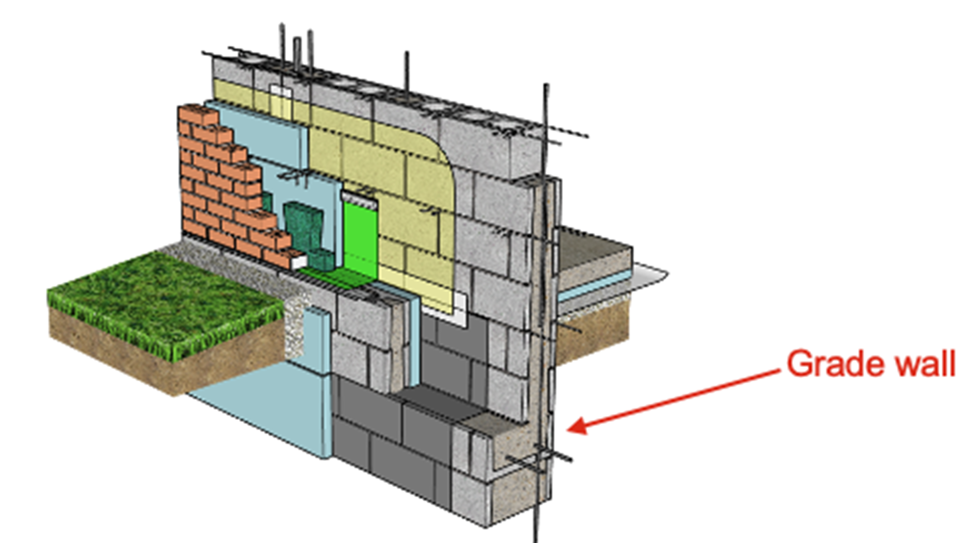 Figure 2 – Base of Wall Detail – Reinforced masonry foundation (courtesy of IMI 3D Warehouse)
Summary:
1. There is no specific code criterion for the placement of movement joints in foundation walls of masonry.
2. Concrete grade walls need no contraction joints for shrinkage. Construction joints should align with masonry movement joints above.
3. Reinforced CMU grade walls should be reinforced to eliminate movement joints using CMHA Technical Note CMU-TEC-009-25.
- Q. An Engineer asks about techniques for adding reinforcement to an existing CMU wall. She wants to create new openings or strengthen an unreinforced area of a wall.
- A. Thank you for the question. Masonry repair and restoration are great topics.
Let’s call the desired additional reinforcement “internal” reinforcement. Two methods for adding this reinforcement that I’ll discuss utilize either mild reinforcement grouted in place or masonry post-tensioning.
Mild reinforcement is the more commonly used method. It is as you stated used for creating new openings or adding reinforcement to strengthen an existing wall. To remove masonry to create a new opening, there are several concerns:
a. The size of the opening and whether shoring is required.
Figure 3 shows a door opening (arrow) being cut next to a previously infilled opening (shown darker). In this case, the masonry was determined to be able to arch over the new opening without shoring. It’s not just the narrow opening that makes this work, but the amount of solid wall above. Each opening needs to be evaluated. (Eye protection is essential!
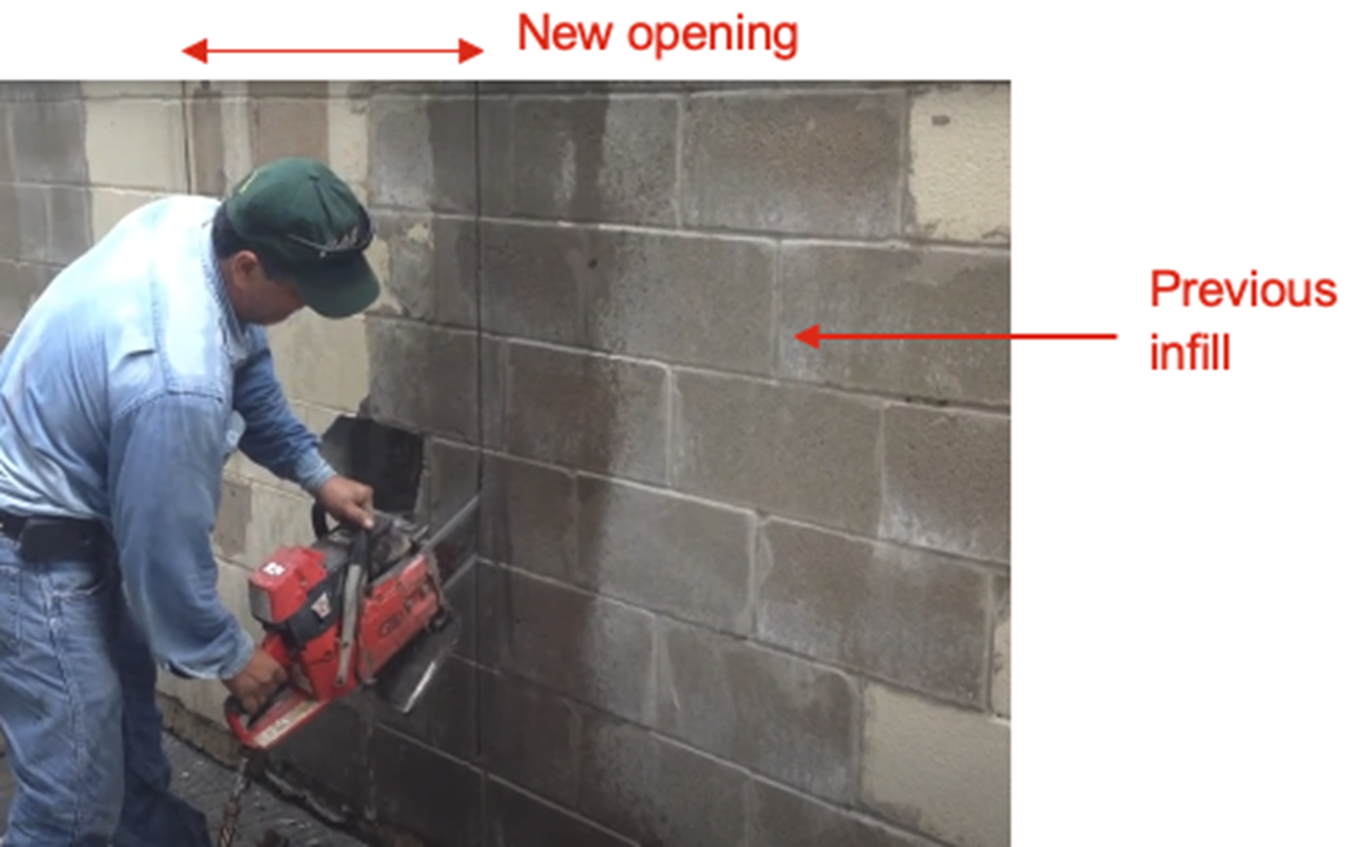 Figure 3 – Cutting new opening (credit: Pavement Services – Houston)
Figure 4 shows a large opening with shoring that was installed incrementally. The opening was cut to receive a new lintel also. Below the end of the opening, the jambs were rebuilt with toothed in half units.
Before cutting any wall, they should be scanned and investigated for embedded conduit or other utilities.
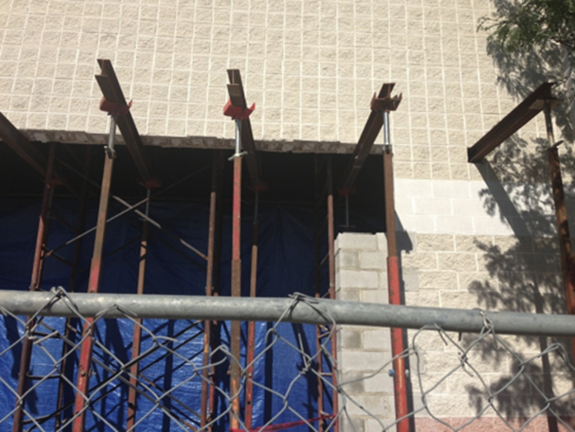 Figure 4 – Shoring and jambs of new opening
b. The placement of the new jamb reinforcement, either before or after cutting the opening.
Figure 4 – Shoring and jambs of new opening
b. The placement of the new jamb reinforcement, either before or after cutting the opening.
In Figure 4, the jambs were rebuilt. The edge cells of the jambs could be cleaned out, the reinforcement added and solidly grouted before the lintel was placed.
Figure 5 shows an interior wall with a new opening where the jambs and lintel are completed.
 Figure 5 – New opening completed
Figure 6 shows a wall where supplemental reinforcement needs to be added. For an exposed interior wall, the complete face shells get removed to form access ports. In this photo, the bottom ports have been infilled. The ports allow for cleaning the cells of excess mortar droppings, lap splice locations, and grouting.
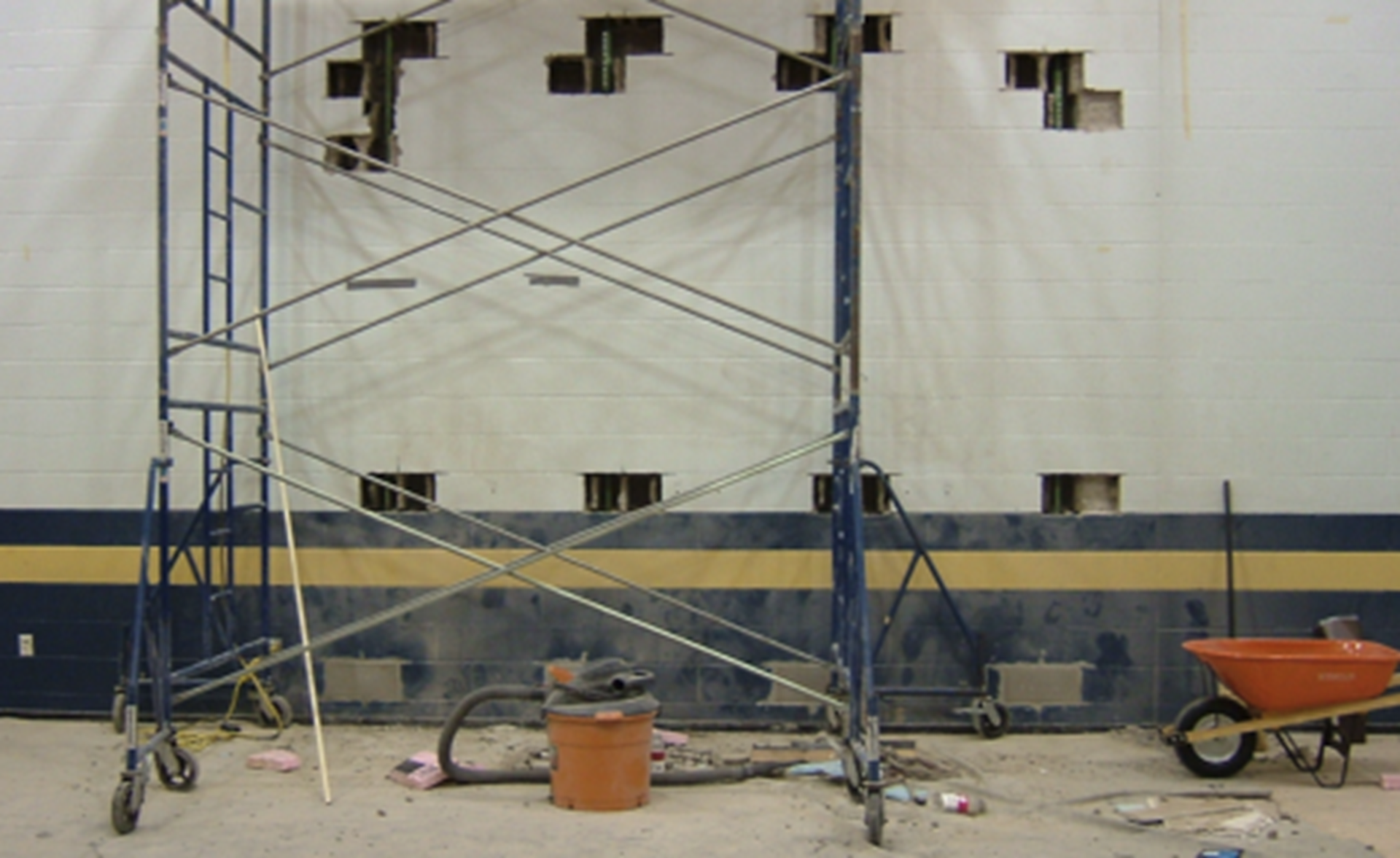 Figure 6 – Access ports for an exterior interior wall
Figure 7 shows ports at the cavity side of a CMU wall. This won’t be seen, so removing the entire face shell is not required.
c. Cleaning the cells, installing the reinforcement, and splicing the bars.
Cleaning the cells is easier when the jambs are rebuilt, as in Figures 4 and 5. In Figure 6, the mason needs to be more creative, possibly using a chimney brush or other tool. Always check that the cells are open and free from blockages for the grout.
The vertical spacing of the ports is selected to accommodate the pour heights or the grout and the length of the bars to be placed. The cell size controls what length bar will fit.
The bottom port size is determined by the engineer as to whether the bars need to be anchored into the foundation or not. If anchored, there needs to be room to get a drill into the wall to embed the bottom bar into the foundation and grout it in place. If not to be anchored, a smaller opening is required (like that shown in the photograph), and the bar terminates at the floor.
When rebuilding jambs at new openings, bars are usually grout-spliced because access is easier. When installing the bars in ports, mechanical couplers are the better choice. Figure 7 shows such a splice. Construction has used mechanical splices for decades; they still are an uncommon sight on masonry projects. Various manufacturers make mechanical splices. It is important to verify the size of these splices to ensure they have adequate clearances per TMS 402 for grout.
The splice shown in the figure provides the full capacity of the reinforcement (Block Lock by Dayton Superior).
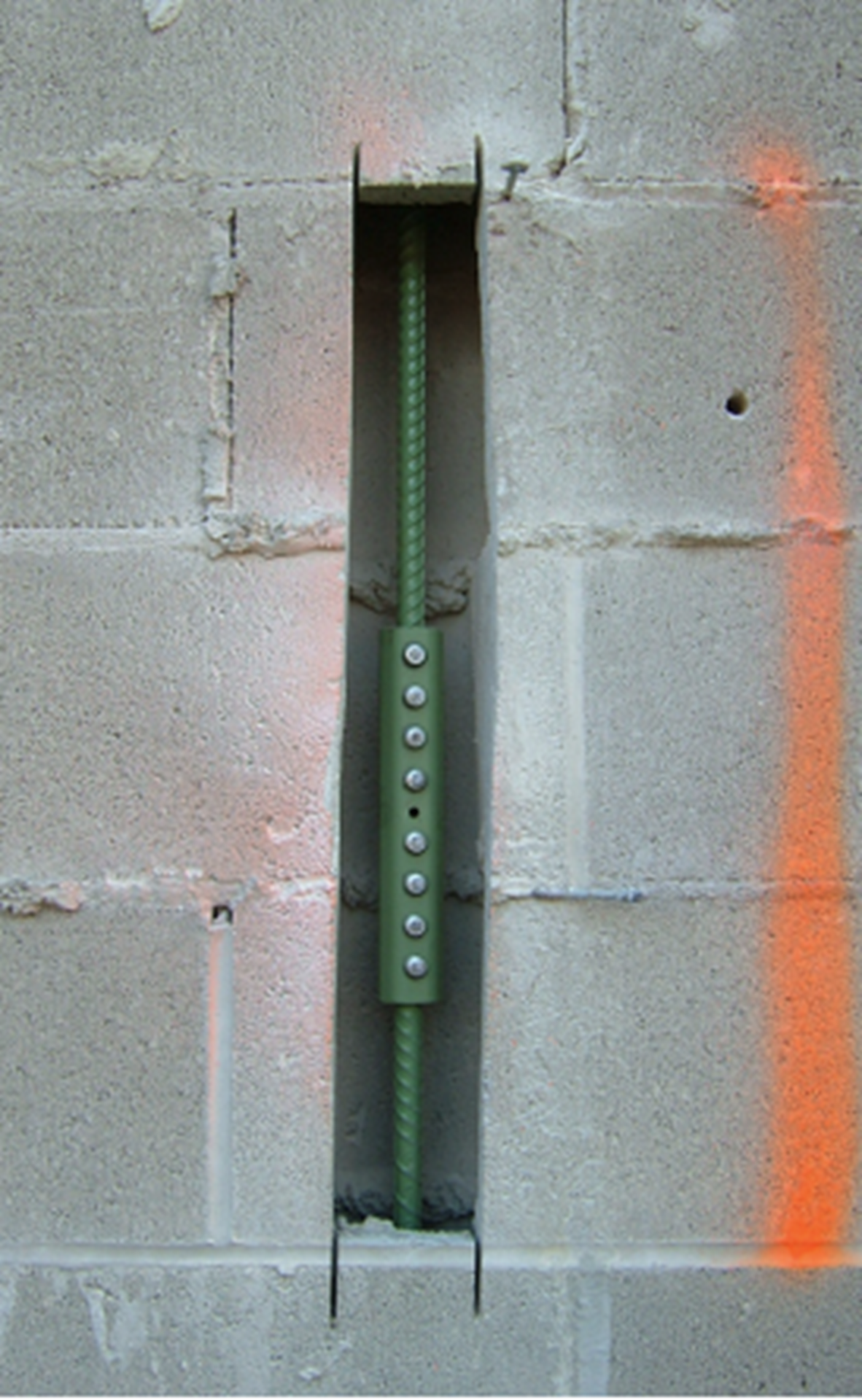 Figure 7 – Mechanical lap splice
Figure 8 shows a threaded reinforcing bar (Williams Form Engineering) that uses a standard low-profile coupler. The threading operation reduces the net area. Be sure to get the rating of the bar with the coupler.
 Figure 8 – Threaded end
Figure 9 has a special end that retains the full bar strength when coupled (nVent/Lenton). It has options for standard couplers.
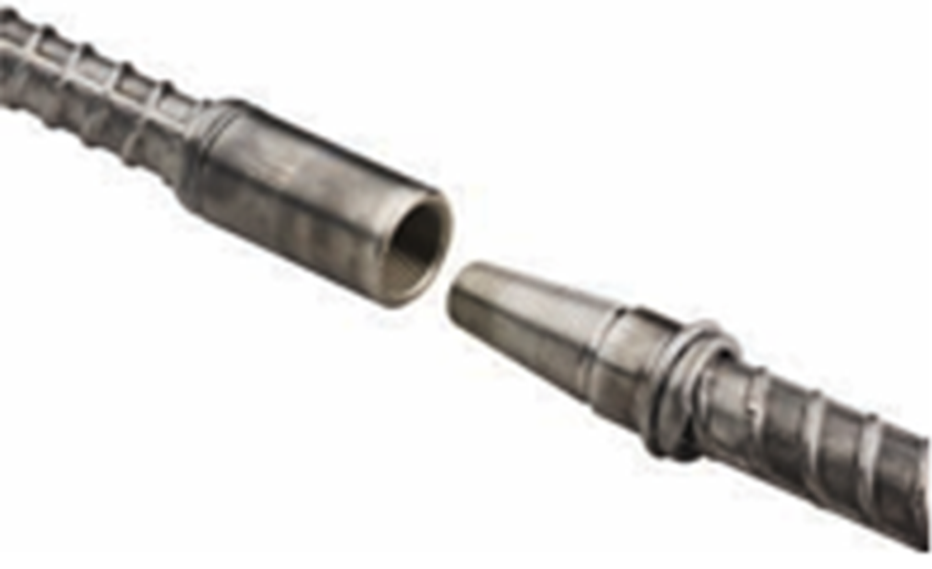 Figure 9 – Specialty threaded end
These are a sampling of available couplers. TMS 402-16, Section 6.1.6.1.3 requires the couplers to achieve at least 125% of the reinforcing bar yield strength. Most couplers are rated for concrete construction as Type 1 or Type 2. Type 1 meets 125% of bar yield strength, while Type 2 meets 160% and is required for high seismic designs in concrete.
d. Grouting and finishing the walls.
Grouting with standard ASTM C476 masonry grout can be challenging with this work because the grout needs to be consolidated and then reconsolidated. Getting the vibrator into the port and down the wall is difficult. Therefore, most contractors prefer to use self-consolidating grout. This does not require either consolidating or reconsolidating and flows easily.
The challenge is that unless the cells have cross-webbing, the grout spreads into the adjacent cells. Some have considered foam-injecting adjacent cells before grouting. It seems like a good option, but I don’t have any results to report.
Only exposed CMU needs to be finished after grouting. Figure 10 shows an interior wall where the face shell was reinstalled and the wall grouted. It will be cleaned and painted.
What can’t be seen is that the face shells were fitted with long stainless steel screws into the back of the face shells. These screws became embedded into the grout and resulted in a mechanical anchorage; they do not rely fully on the perimeter mortar bond.
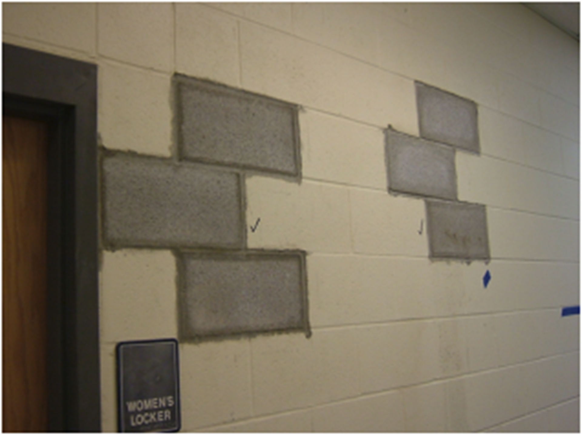 Figure 10 – Interior wall after grouting
Figure 11 shows the finished grouted wall in a cavity wall before the barriers, insulation, and veneer were replaced. The grout was formed smoothly.
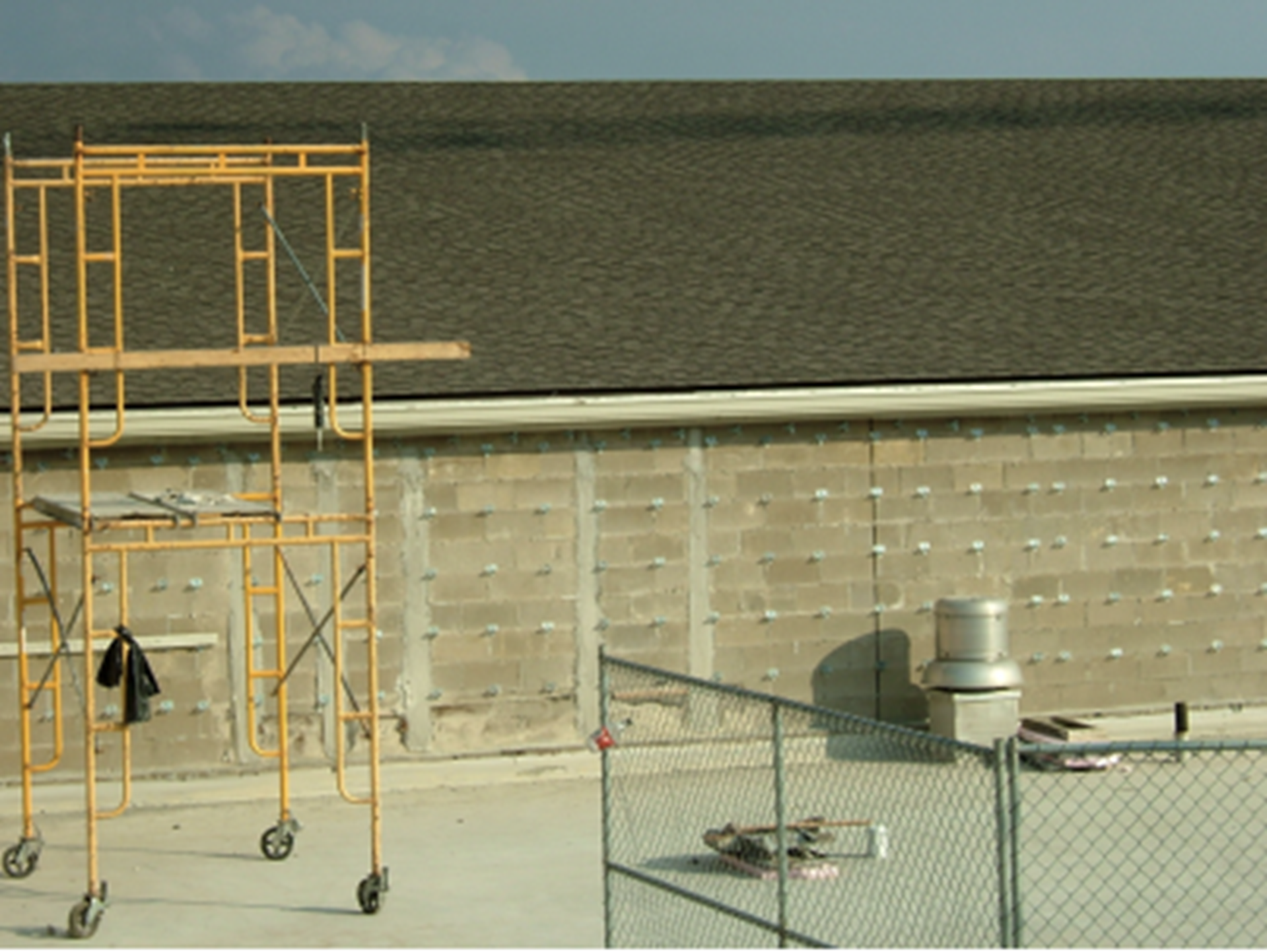 Figure 11 – Cavity wall side of CMU grouted
The second method requires masonry post-tensioning. Bar reinforcement is used as post-tensioning tendons and requires ports the same as the last method. The benefit of this method is that it can be done with little or no grouting.
Figure 12 shows an example of a wall to be strengthened for out-of-plane action, not shear. It is a CMU wall with a brick veneer. To avoid damaging the veneer, the access ports were installed on the inside face.
 Figure 12 – Cavity wall elevation
Figures 13 and 14 show the interior ports. The existing cells of the CMU had foam insulation. Cleaning the cells was avoided by using post-tensioning. The bars could be pushed through the insulation.
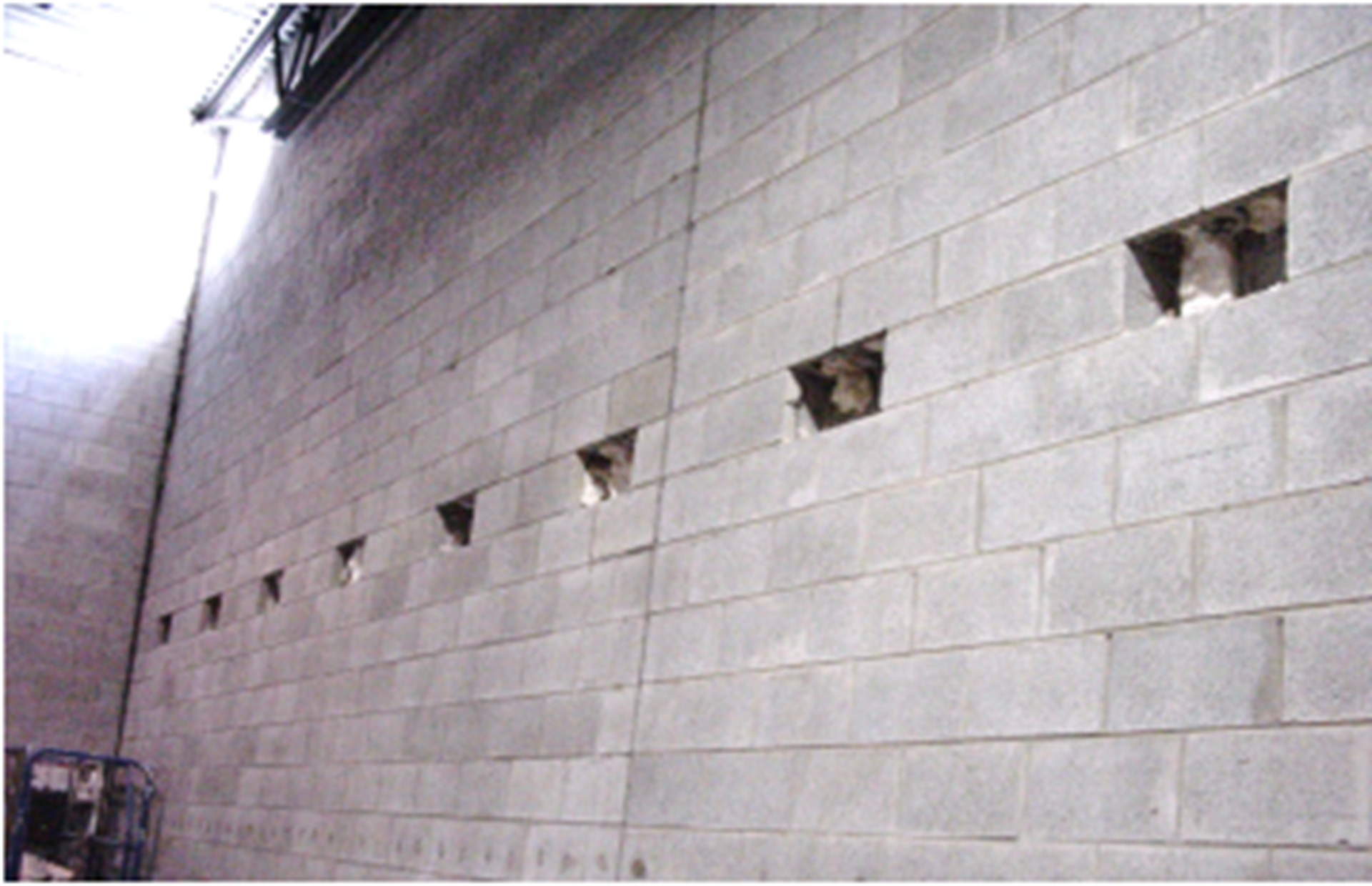 Figure 13 – Upper ports
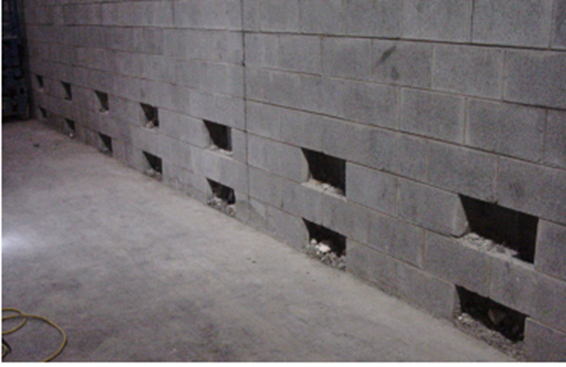 Figure 14 – Lower ports
The bottom anchors were grouted in place into the lower port (Figure 15). The second port above was the first lap for the bars.
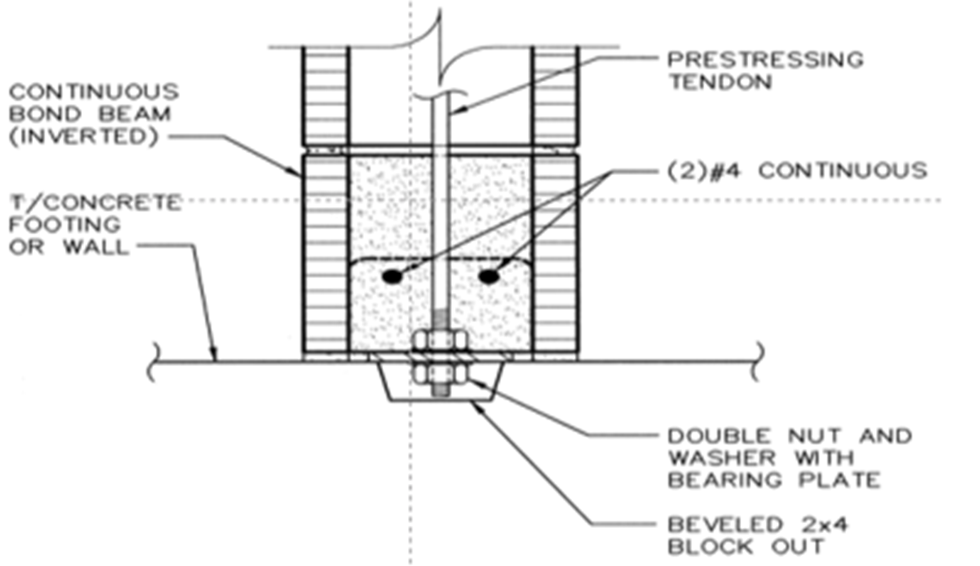 Figure 15 – Bottom anchor
The post-tensioning reinforcement was designed using TMS 402 using the Prestressed Masonry chapter. The only grout was at the bottom and top.
The method currently applies to Seismic Design Categories A and B. Grade 60 reinforcing bars with threaded ends were dropped down through the wall by removing the coping. The top bearing was grouted solid and tensioned (Figure 16) to approximately 6,000 lbs. each.
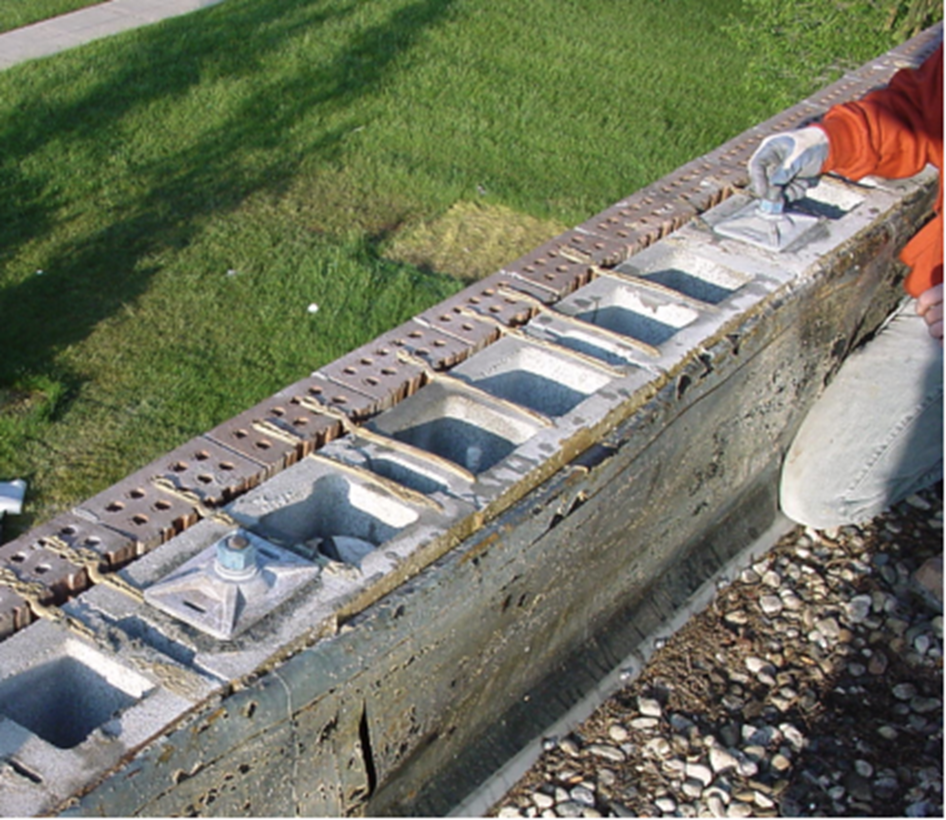 Figure 16 – Top of wall
Summary:
1. Walls can be strengthened using grouted reinforcement. In low seismic zones, post-tensioned masonry is another option for low seismic zones.
2. Confining the grout to the desired cells is one of the biggest challenges.
3. Self-consolidating grout is preferred over standard grout. Both are specified using ASTM C476.
4. Thanks go to Scott Walkowicz, PE, FTMS, NCEES, Walkowicz Consulting Engineers, for this example and the photographs.
Thank you again for following this column. Remember, by bonding, we get stronger! Keep the questions coming. Send them and your comments to info@masonrymagazine.com, with attention to Technical Talk. If you have missed any of the previous articles, you can find them online for Technical Talk, Bonding with Masonry at Masonry Design magazine.
David is a PE, SE with Biggs Consulting Engineering, Saratoga Springs, NY, USA (www.biggsconsulting.net), and an Honorary Associate Professor with the University of Auckland, NZ. He specializes in masonry design, historic preservation, forensic evaluations, and masonry product development.
Keywords for this issue: masonry, movement joints, foundations, strengthening CMU walls, new openings, post-tensioning