Joint reinforcement: Less is more

Words: Daniel AbitboulDo you still encounter project specifications that require (often or occasionally) truss-shaped wire, heavy-duty wire, prefabricated corners and/or Ts? If so, it’s time to climb the ladder, so your company can positively impact the constructability, performance and cost effectiveness of your client’s projects.

Far too many specifications for horizontal joint reinforcement inadvertently include requirements that could undermine the capacity to meet code and negatively impact the constructability, performance and cost effectiveness of reinforced CMU wall systems. Some requirements are simply an unnecessary waste, while a few, like prefabricated Ts for intersecting walls, may even elevate safety concerns.

Mason contractors can empower themselves to intervene (prior to or during the submittal process) to educate the project designers and construction professionals with myriad code compliance and performance data available. There should be receptive ears, because no one wants to take responsibility for requiring you to proceed with an installation linked to specifications that could undermine your capacity to meet the code.

Another benefit of this exercise is, when successful, you will not only positively impact the particular project at hand with updating the designer’s master specifications, but will have a domino effect on future projects.

The main objective of this article is to provide you with tools (knowledge) that support the premise “less is more,” when it comes to using horizontal joint reinforcement. We begin with a brief history including why, where and what wire is, including many factors that impact its use. We also touch on corners, intersections and finishes. Finally, we present a generic specification that provides IBC and TMS Code compliance with an eye on improved constructability and economy.

History

According to the National Concrete Masonry Association (NCMA) TEK 12-2B (2005) Joint Reinforcement for Concrete Masonry: “It was initially conceived primarily to control wall cracking associated with horizontal thermal or moisture shrinkage or expansion and as an alternative to masonry headers when tying masonry wythes together.”

This TEK Note goes on to state that it “…also increases a wall’s resistance to horizontal bending, but is not widely recognized by the model building codes for structural purposes.”

The most dramatic design change in single- and multi-wythe masonry walls, since wire reinforcement became the norm in the 1960s, was the shift to vertical and horizontal steel reinforcement (rebar) in CMU (block) in the 1990s. This encompassed all of North America’s unreinforced markets, not just seismic zones.

According to NCMA TEK 10-3 (2003), Table 2 (Maximum Spacing of Horizontal Reinforcement to Meet the Criteria As > 0.0007 An) for un-grouted or partially grouted walls vertical spacing of wire is 16 inches on center for eight- and 12-inch block. Additionally, Table 2 states the 16-inch spacing applies to nine-gauge wire with two wires (one wire per face shell of the block). Rare is a CMU wall without frequently spaced vertical rebar and corresponding bond beam(s) with rebar encapsulated in grout.

Rebar placement

When structural engineers design reinforced masonry, they typically call for the vertical bar to be placed in the center of block cells. The masonry code requires placement tolerance for vertical rebar to be +/- ½ inch (across the width of the block) and +/- two inches (along the length of the block) measured from the center of the block cell (Masonry Standards Joint Committee, The Masonry Society (TMS) 2011 Specification: Articles 3.4 B. 11. a & b).

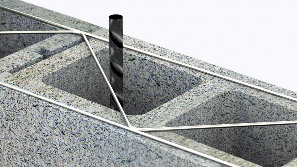
Figure 2: Truss-shaped wire interferes with code-required rebar centering, and may cause grout to hang up on the diagonal wires.

Shape matters

Ladder-shaped wire has perpendicular cross-rods butt welded at 16 inches on center to the longitudinal wires. It’s placed with cross-rods centered directly over the webs of the block (see Figure 1). Placement of ladder wire in this manner eliminates obstructions caused by diagonal cross-rods common with the truss shape, especially where block cells are designed to contain vertical bars (see Figure 2).

Grout flow

Another advantage of ladder wire is evident when grout is placed and consolidated. The absence of diagonal (truss) cross wires improves the flow and consolidation of grout. Typically, the masonry code requires block (hollow units) to be placed so vertical cells to be grouted are aligned, which provides an unobstructed path for grout flow (TMS 2011 Specification: Article 3.3 B. 3. D). According to NCMA TEK 12-2B, “….because the diagonal cross wires may interfere with the placement of vertical reinforcing steel and grout, truss-type joint reinforcement should not be used in reinforced or grouted walls.”

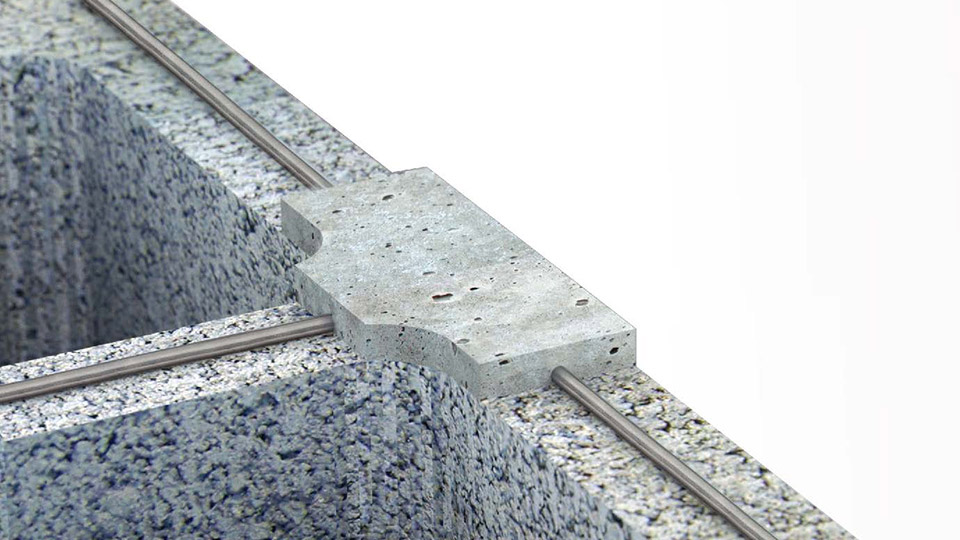
Figure 3: Ladder-shaped wire improves shrinkage control by forming interlocking Ts at cross webs.

Shrinkage control

Ladder wire placed with cross rods centered directly over block webs has yet another distinctive advantage. It positions butt welded “T” intersections of each longitudinal wire with cross rods directly over “T” intersections, where block face shells meet each web. When laid in running bond pattern, two-cell block are placed with face shell (exterior and interior) mortar bedding only. Block webs are only mortar bedded adjacent to vertically reinforced cells. Face shell mortar bedding will extrude at the webs when compressed during block placement, completely encapsulating the wire “T” intersections, bonding the wire to the concrete masonry (see Figure 3). Hence, the net result should be improved shrinkage crack control.

Standard nine-gauge vs heavy-duty 3/16-inch

Besides its shape (truss or ladder), wire thickness is important in the placement process. The most common mortar joint thickness specified is 3/8 inch. The maximum wire diameter allowed by the masonry code would be one-half of the 3/8-inch mortar joint thickness, or 3/16 inch [TMS 2011 Code: Section 1.16.2.3]. However, there are compelling reasons to use the smaller size nine-gauge wire.

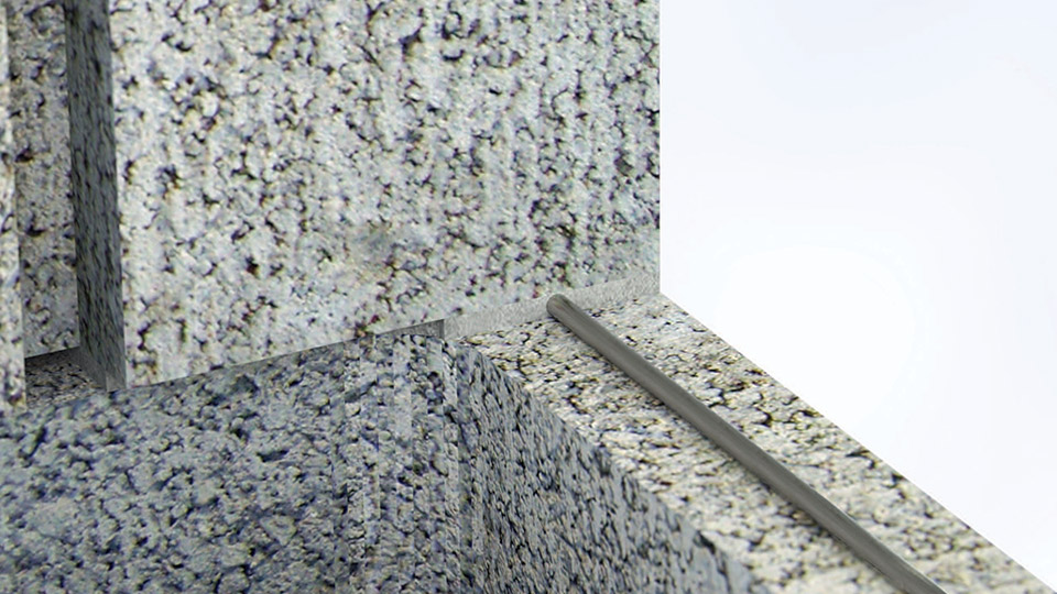
Figure 4: Heavy-duty, 3/16-inch-diameter wire can leave inadequate room for proper mortar coverage. Both the top and bottom of wire could be in direct contact with masonry unit (no mortar coverage).

Placement tolerances

The masonry code tolerance for the placement of the mortar bed joint thickness is +/- 1/8 inch [TMS 2011 Specification: Article 3.3 F. 1. b.]. Therefore, a specified mortar joint of 3/8 inch would be allowed to vary from ½ to ¼ inch in thickness. With an as-built mortar joint thickness of ¼ to 3/8 inch, using heavy-duty 3/16-inch wire with hot dip galvanized coating [TMS 2011 Code: Section 1.16.4.2] could leave inadequate room for mortar cover encapsulation (see Figure 4) when considering the galvanized coating, the levelness of the top surface of the CMUs supporting the wire and the planeness of the wire.

Quite literally, block could be placed directly on the wire (block on wire on block). According to an article by Mario J. Catani in the January 1995 Masonry Construction magazine entitled, “Selecting the Right Joint Reinforcement for the Job,” he states, “One compelling reason to use nine-gauge reinforcement is for fit and constructability. While the code allows joint reinforcement to have a diameter one half the mortar joint width, the tolerances allowed for units, joints and the wire itself can hinder the placement of large diameter reinforcement. Use it only when there is no other choice.”

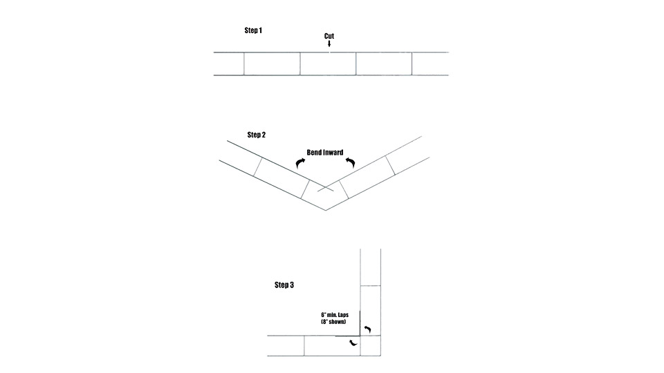
Figure 5: A simple, three-step sequence to field form corners.

Forming corners

There is some debate regarding the merits of ordering factory prefabricated inside and outside corners versus field-forming them. Since the TMS Code does not distinguish the merits of either method (and, indeed, barely recognizes them), some commentary is warranted. The industry standard for lapping wire reinforcement at any location is always the same: It requires at least six inches, whether lapping straight 10-foot sections one to another, or where a straight section meets a corner (TMS 2011 Specification: Article 3.4 B.10.b). This requirement also can be applied to field-formed corners. The inside longitudinal wire can be cut and bent to form a 90-degree angle with a minimum of six inches of lap paralleling the newly formed inside longitudinal wire (see Figure 5).

Factory-prefabricated corners may seem like the natural choice, but this can require additional lead time and cost for any size or configuration other than standard eight- or 12-inch, two-wire reinforcement. This is especially the case for custom-made adjustable hook-and-eye configurations.

Figure 6: Code-approved mesh ties are safe, economical and readily available.

Intersecting walls

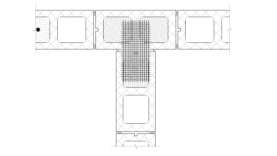
TMS Code allows prefabricated T-horizontal wire reinforcement sections, where an interior non-loadbearing masonry wall intersects another for lateral support. However, this may not be the best selection. Such T-sections are typically embedded 16 inches on center during construction in the longitudinal wall, leaving the projecting leg of the T-section extending out about 24 inches until the intersecting wall is constructed.

Many masons will agree the exposed wire sections can be dangerous onsite, especially at eye height. Fortunately, the TMS Code also allows ¼-inch mesh galvanized hardware cloth for interior non-loadbearing interesting walls (see Figure 6). Additionally, the TMS Code requires Z-strap anchors for walls that intersect where shear transfer is desired. Projecting Z-straps pose similar safety concerns with exposed T-sections.

However, they only need to be used when the design requires shear transfer, which is often misunderstood by the design community. When applicable, mesh ties are typically the best choice. They are readily available, simple, and economical to install, and can be safely bent out of the way until the intersecting wall reaches their height.

For intersecting interior loadbearing walls, lateral support is usually achieved from supporting framing members, and is not dependent on intersecting walls for lateral support.

Finish options

The two most common finishes for wire reinforcement are mill galvanized and hot-dip galvanized. The first category is allowed by the TMS Code for most interior applications not in contact with moisture or high humidity. Standard mill galvanized finishes are produced through electro-galvanization, a process where a layer of zinc is bonded to steel when a current of electricity is run through a saline/zinc solution with a zinc anode and steel conductor. This process is undertaken when wire is in its raw state, before fabrication (i.e. cut and welded to shape) into wire reinforcement.

Hot-dip galvanization is required for all exterior applications, as well as any interior walls exposed to moisture or high humidity. It is a process of coating steel with a heavy layer by immersing it in a bath of molten zinc. This process is undertaken after wire is fabricated to form reinforcement.

In a few unique applications, stainless steel might provide value. Though very expensive, it may be necessary in high-corrosive environments or where non-magnetic requirements are necessary.

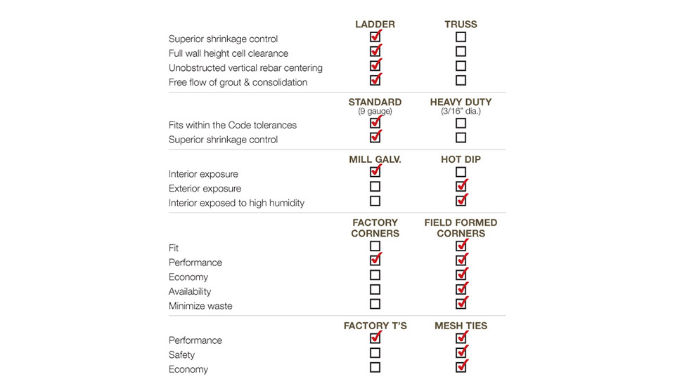
Figure 7: This guide outlines joint reinforcement selection.

Myriad advantages

Unfortunately, not all who design or specify wire reinforcement have kept pace with the shift to reinforced CMU. There are many pockets of the country where antiquated truss shape and/or heavy-duty wire are still in use. Figure 7 reviews the advantages of ladder and disadvantages of truss, along with standard nine-gauge versus heavy-duty wire reinforcement.

Additionally, ladder-shaped wire with nine-gauge side- and cross-rods has other advantages including lower production, packaging and shipping costs. Lighter bundle weight reduces risk of back injury when they are handled on the jobsite. Ladder configuration also streamlines wire, rebar and grout installation. This, in turn, enhances bricklayer productivity.

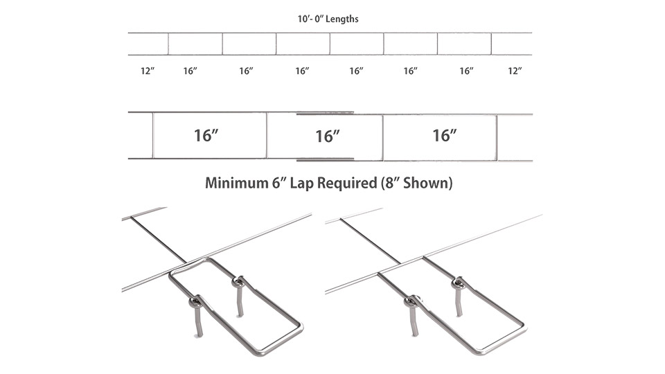
Figure 8: Ladder-shaped wire, code-required minimum lap, and butt-welded adjustable eye options are shown here.

Generic specifications

The following, and Figure 8, provide an example of the recommended wording for horizontal joint reinforcement in single- and multi-wythe masonry walls:

Part 2 products

2.1 Masonry Reinforcing
A. Joint Reinforcement, General: ASTM A 961
1. Interior Walls: Mill galvanized, ASTM A 641 (0.10 ounces per square foot), carbon steel
2. Exterior Walls: Hot-dip galvanized, ASTM A 153 Class B-2 (1.50 ounces per square foot) carbon steel
3. Interior Walls Exposed to High Humidity: Hot-dip galvanized, ASTM A 153 Class B-2 (1.50 ounces per square foot) carbon steel
4. Wire Size and Side Rods: W1.7 or 0.148-inch-diameter (nine-gauge)
5. Wire Size and Cross Rods: W1.7 or 0.148-inch-diameter (nine-gauge)
6. Wire Size for Veneer Ties: W2.8 or 0.1875-inch-diameter (3⁄16 inch)
7. Spacing for Cross Rods: 16 inches on center
8. Provide in lengths of 10 feet

B. Masonry Joint Reinforcement for Single-Wythe Masonry: Ladder type with single pair of side rods

C. Masonry Joint Reinforcement for Multi-Wythe Masonry: Ladder type with adjustable (two-piece) design, with separate double-eye butt welded to side rods 16 inches on center; double hook ties that engage eyes welded to reinforcement and resist movement perpendicular to wall. Hook tie length shall be sufficient to extend 1⁄2-inch minimum into outer face shell for hollow units and 1.5-inch minimum into solid units, but with a minimum 5⁄8-inch cover at outside face.

Conclusion

Mason contractors can positively impact the constructability, performance and cost effectiveness of their projects, all with the added benefit of upgrading the designer’s specifications to better meet code requirements.

To control potential shrinkage cracking in a concrete masonry wall, it requires proper placement of the control joints and horizontal joint reinforcement. Horizontal joint reinforcement in a CMU wall does not prevent cracking, but, rather, controls it. Without it in a concrete masonry wall, shrinkage cracks may be visible and of a size more easily penetrable by Mother Nature.

With nine-gauge, ladder-shaped joint reinforcement in a concrete masonry wall, the longitudinal wire goes into tension as the concrete masonry is shrinking. Hence, an occasional microscopic crack should not be noticeable and would be less vulnerable to the elements. Use of truss-shaped wire that must be altered to fit around vertical reinforcing may not meet code compliance and may negatively impact the integrity of a reinforced concrete masonry wall system.

In summary, with respect to the statement “could undermine the capacity to meet code,” consider the following: Ladder wire, when placed correctly, will not interfere with the minimum code requirement for placement tolerances of the vertical bar. Ladder wire, when placed correctly, will not interfere with meeting the minimum code requirements for placing and consolidating grout. Standard nine-gauge wire would leave more room for mortar cover encapsulation, when the mortar bed joint thickness is constructed within the minimum code tolerances.

When it comes to masonry wire reinforcement, the old adage “less is more” holds true. Ladder wire, fabricated in 10-foot lengths with nine-gauge continuous side rods and butt welded nine-gauge cross-rods spaced 16 inches on center is the ideal for high-performance CMU wall systems.

Field-formed corners and mesh ties at intersections offer greater performance, economy and safety. Meet code and performance requirements with standard mill galvanized for interior and hot-dip galvanized for exterior and high-moisture or humid environments.
About: Featured
LAR 300 Rotary Laser – Rugged, Precise, and Efficient Horizontal Leveling Made Easy

STABILA’s reputation for high-end measuring products and German engineering shines through in the LAR 300 Rotary Laser. This laser combines simple functionality with high precision across large distances and unmatched durability. Key Features Precision an

The Roman Empire – Hadrian’s Wall , Great Britain

In this article, we travel to the island of Great Britain, a land known for its Marvelous Masonry. From such icons as Stonehenge, Westminster Abbey, Big Ben Clock Tower, and their brick arch railway bridges, masonry has been the dominant building material

Vibing Masonry: Masonry for Safety, Security & Protection

Masonry conveys protection, shielding occupants from external threats. Masonry also provides strength and resistance—separation from and resistance to fire, resistance against projectiles and ballistics, robust defense against vandalizing mobs and spontan

About: Featured
“Elevated Safety” on Masonry Construction Sites: The Value of EZG's Hog Guard and Hoist Hog

In the bustling world of construction, safety isn't just a priority—it's a foundation. Nowhere is this more crucial than on masonry sites where block structures rise skyward. Each day, workers navigate scaffolding, maneuver materials, and tackle tasks tha