
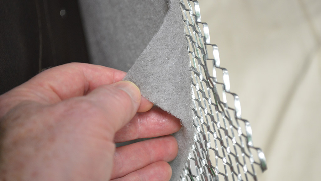
Figure 2 — Self-furring metal lath with mesh drainage plane.
Cavity wall construction became popular in the 1920s in Northwest Europe. However, in our lifetime it became more popular with the energy crisis in the early part of the 1970s. Due to the economic needs of wall construction, the need to conserve energy and the available insulating materials, the cavity walls we are now familiar with became the standard. The walls we are discussing tie the wythes (pronounced why-th-s) together with metal ties, a design that became popular and economical after header brick (which tied many walls together early on) became a thing of the past. In the seventies, many of the walls were still constructed of cinder block or clay tile backup and brick veneer. Copper fabric flashings, invented in 1935, were not widely used. The creation of air barriers had not yet come about, and damp proofing, used primarily below grade, was slowly becoming a product used above grade in the cavity between the wythes. Later, as envelope science advanced, the bituminous, non-elastic damp-proofing was added to the outside face of the substrate walls. Damp proofing reduced the moisture that entered the wall mainly during construction, but was somewhat effective throughout the life of the building.
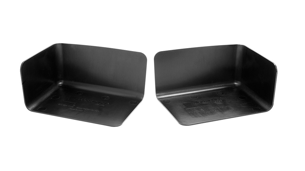
Figure 3 — Pre-formed one-piece end dams
End dams (Fig. 3) should always be used at the termination of any flashing. The old-school thinking that the water will just drip into the cavity and evaporate is a gamble that is not worth taking financially. The installation of an end dam, whether you purchase a premade piece or pull and tuck your flashing membrane, will cost the mason about $5 on each side of the flashing. Compare that to three times a mason’s hourly rate to fix the problem, plus overhead, plus profit. It’s three times the wages because (1) he loses the original installation, (2) he needs the time to fix the original installation, and (3) there is another job he could have done while fixing the original installation.
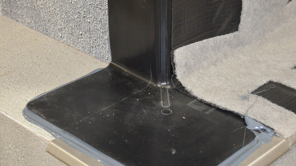
Figure 4 — Pre-formed one-piece outside corner boot.
Flashings can be installed from right to left or left to right. The latter is how I prefer to install them. Flashings begin at either an inside or outside corner and should be installed with the corner boot (Fig. 4) placed on top of the drip edge (if a drip edge is used); otherwise they should be installed on the corner first. Again, either purchase a premade component or field fabricate a boot; either way, it must extend to the top of the flashing, be installed above the drip edge and have complete perimeter sealant so when applied to the substrate, water cannot penetrate behind the boot. Once the components are installed, you are ready to install your flashing.
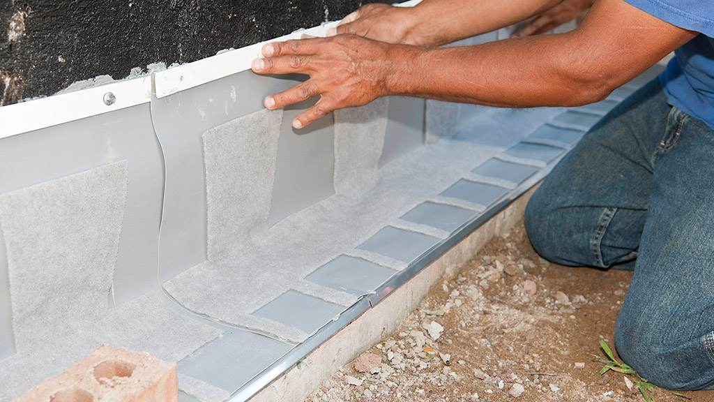
Figure 5 — Prefabricated flashing panels.
A termination bar has become the current standard for attaching flashings to the substrate. There are manufacturers that promote rubberized asphalt applied with a primer that does not require a term bar. But, why take chances on a chemical bond to hold the flashing in place when for a few dollars more a term bar will hold it mechanically in place for the rest of your career as well as your children’s careers?
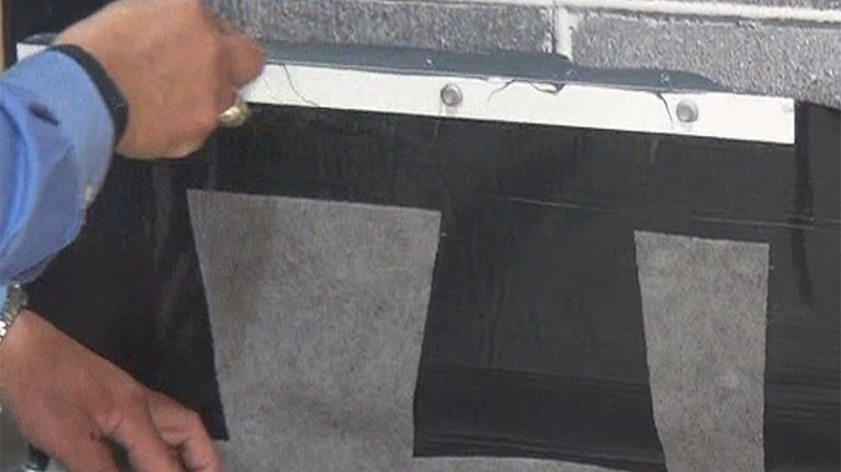
Figure 6 — Creating a proper seal at the top of a termination bar.
Drive pins are commonly used around the country with success. However, if driven too tight, the termination bar may become deflected and create opportunity for leaks. When I install a termination bar, I want to mount the product to the wall. I do not want to wear a tube of sealant on my hands, shirt and pants, so I recommend pre-drilling your anchor holes, threading the screws through the termination bar, then placing the sealant on the backside of the termination bar, not the substrate wall, and snug the termination bar into place. This will be a cleaner application with less waste. When you snug the termination bar into place, the excess sealant you put behind the bar will ooze up and provide you with the required material to slick at the top of the bar (Fig. 6). By slicking the excess material, it will allow any moisture that comes down the wall to bridge over the termination bar onto the flashing without using any additional material.
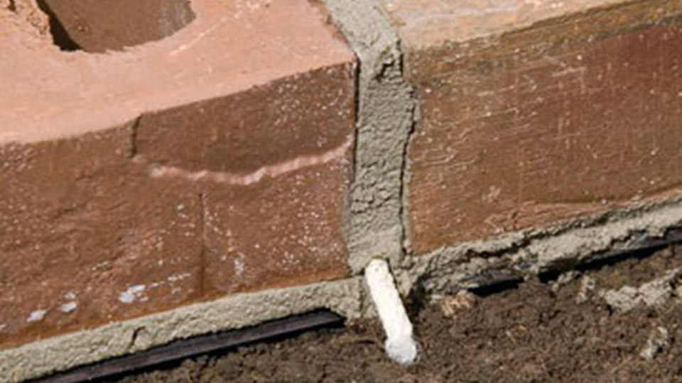
Figure 7 — Cotton rope wick — not recommended.
I have worked on many school projects where the CMU is installed at an earlier time than the exterior veneer, and in some cases masons prefer to install the flashings in between the courses of block. In cases where the flashing is to be exposed for several months, there are a few things that can happen. The construction process can inadvertently puncture the flashings, which can compromise the materials. When this happens, the contractor can usually place another piece of flashing under the damaged piece of flashing and attach it to the substrate using a termination bar directly under the bed joint where the original piece of flashing is installed, then attach the new piece of flashing just as he would with a standard lap on both sides. This keeps the integrity of the original flashing intact. It is recommended to seal the puncture so as not to allow moisture to form in an isolated pocket.