Designing With Masonry
Words: Steven JuddWords: Steven Judd
Photos: Steven Judd
It is unreasonable to expect masons to do a structural design, and for the most part, to do any code interpretations related to design for projects that have drawings and specifications issued for bidding and construction. It may however be beneficial to gain some background in the reasons why designs and details are the way they are, which is usually based on one or two things:
1.) What the code requires (which changes periodically)
2.) The preference of the designer, based on their collective experience (which is usually based on problems encountered in the past and “engineering judgment”).
Reinforced Masonry – Concrete Masonry Units (CMU) and Hollow Clay Masonry units (HCM)
This section of the article assumes structural masonry units are 16” in nominal length with two large cells intended to receive reinforcing and grout, or other fillers. Structural masonry units do come in 12” (nominal) lengths which will then change the typical vertical rebar spacing module to 6”, rather than the typical 8”, however these 12-inch-long units are not very common.
Reinforced masonry is also called structural masonry. The design and detailing of walls and building systems composed of structural masonry units is much the same as reinforced concrete. In some ways, CMU (ASTM C90 compliant ) – see Figure 1, and HCM (ASTM C652 compliant) – see Figure 2, can be considered ‘left-in-place’ forming which is intended to be filled with reinforcing and concrete – concrete in this instance called “grout”. The left image in Figure 1 is called a “stretcher” unit (having recessed end webs) in some regions of the US and Canada, while the right image is called a “jamb” or “corner” unit, in some regions of the US and Canada.
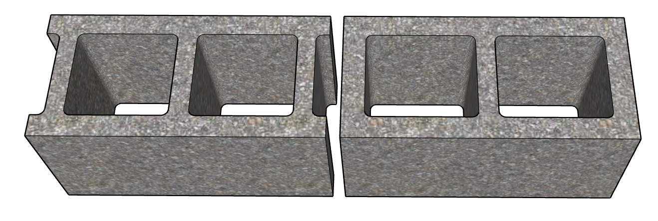
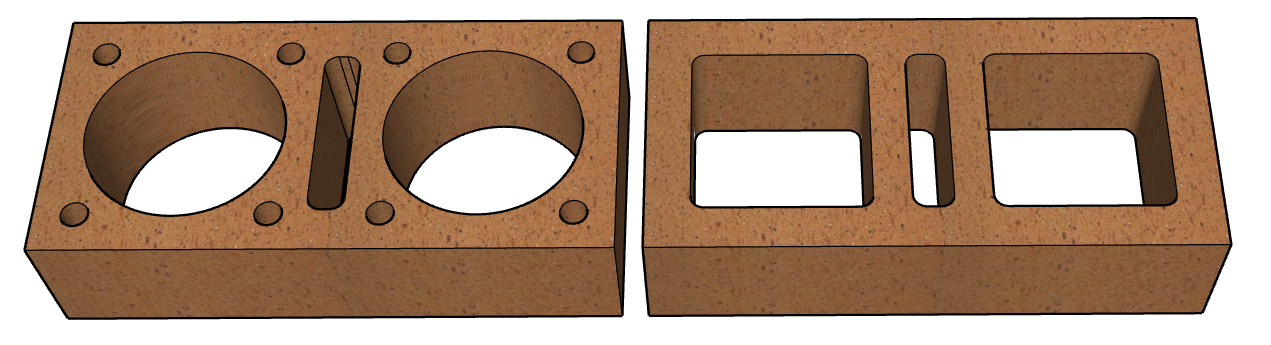
Figure 1: CMU w/ recessed & flush end webs Figure 2: HCM w/ typical cell configurations
As seen in the images in Figures 1 and 2, there will be common situations where grout will not fill every void. For CMU stretcher units (the left-hand image in Figure 1) the void created at the head joint will fall directly below the center web of the unit in the next course above, which has the potential to block the flow of grout into the head joint void, resulting in unfilled space.
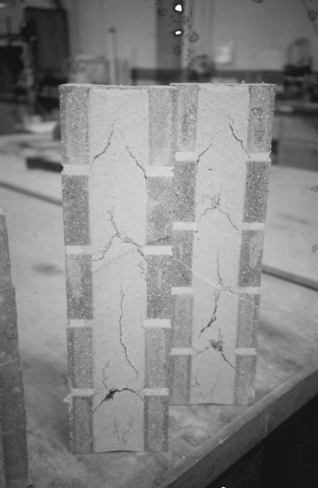
Grout in structural masonry is different from grout in tile work. “Grout”, as used in structural masonry (we’ll call it ‘structural masonry grout’), is basically a special concrete mix with a fairly high slump (typically 8” to 11” slump), consisting of fine and coarse aggregate (sand and pea-gravel, respectively), plus cementitious binder (usually portland cement), plus water, and sometimes admixtures to modify the properties of the mix. [Grout, as used in tile work, is basically a joint filler which may be made of very fine sand, water, a binder (cementitious material), pigment, and water.] “Fine” structural masonry grout, which is produced without the pea-gravel, is typically used for areas with restricted grout flow potential and/or areas of congested reinforcing. Structural masonry grout placement requires initial consolidation at the time it is placed and reconsolidation approximately 20 minutes later; after the initial consolidation, after excess moisture in the grout mix has been absorbed by the masonry units; before the mix starts to set up and become rigid. Time intervals may vary. Without proper consolidation and reconsolidation, fissures, cracks, or voids (sometimes called “grout rivers”) can be created in the grout as the excess moisture leaves, and the grout column attempts to get pulled downward due to gravity. See figure 3.

Standard mortaring of the units only requires mortar around the periphery of the unit to a depth to match the thickness of the face shell, so the majority of the head joints will have a 3/8” wide void as well. This is very narrow and should be assumed to remain a void where standard coarse grout is used.
For HCM, the narrow center cell of the units shown in both images, and the small circular cores of the left-hand image as shown in Figure 2 are likely to never be filled with standard coarse grout. The center cell falls directly below the head joint of the course above, which is only 3/8” wide, as discussed with the CMU. It is generally not necessary to go to any unusual or extreme means to ensure these ‘naturally occurring’ voids get filled. If the construction documents have specific language about filling all voids, it would be prudent to issue a request for information about the naturally occurring voids as outlined above. Some masonry unit manufacturers have tables of equivalent solid thickness based on the assumed voids based on the profiles of their specific units. If not available, it should be requested.
Detailing of the reinforcing at wall intersections – “L”, “T”, and “X” or cruciform intersections – see Figure 4 - are critical to the design of the wall system, and potentially the stability of the entire structure. Some wall intersections are intended to have the adjoining walls remain somewhat independent, and other intersections require continuity such that forces (sometimes significant forces) can be transferred across and through the intersection. Integral intersections – intersections where structural continuity is required – can be toothed together, where possible, and generally have continuity of horizontal reinforcing tying the abutting walls together. Careful review of the drawings is necessary to ascertain how the wall intersections are treated. Adding a joint at a wall intersection may detrimentally impact the design of the project. If uncertain, create a request for information to clarify.
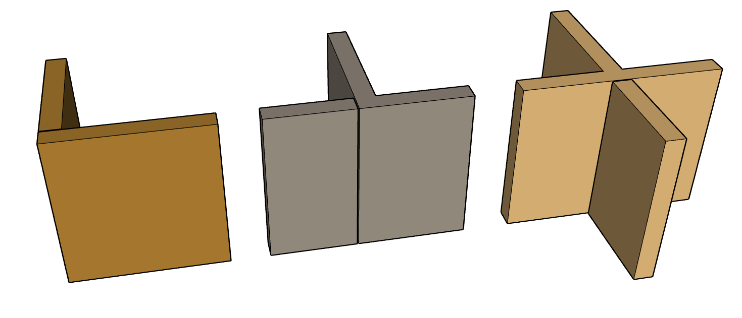
Figure 4: “L”, “T”, and “X” or cruciform intersections, left to right, respectively
Critical items in structural masonry are the size and spacing of the reinforcing bars (rebar) making sure they are placed in the correct locations; making sure laps lengths are sufficient for continuous bars (typically vertical bars in walls and horizontal bars in bond beams), and bar extensions past the edge of openings (trim bars around door and window openings).
Some designs – probably most designs – will have single bars centered in the grouted cells. Vertical rebar spacings can vary from 8” on center (rebar in every large cell) to 120” on center in some cases for interior walls in low seismic areas. Some designs, where more strength is needed, may have two bars per grouted cell, usually spread a part
High-lift grouting may require rebar positioners to hold the vertical bars in the correct location. Low-lift grouting generally does not use rebar positioners, so it is the mason’s responsibility to make sure the reinforcing remains in its proper location during the grouting, consolidation, and re-consolidation process.
It is not uncommon for some engineers to design hot-rolled structural shapes (steel beams or angles) to be used to span across openings (doors and windows)
Reinforced Masonry – multi-wythe reinforced face brick walls.
Reinforced masonry walls can be designed and constructed using face brick, rather than using CMU or HCM.
It is not practical to reinforce typical face brick units (ASTM C216 compliant), for two reasons: 1) units may be solid with no cores, and 2) units that are cored tend to have very small cores which are not conducive to placing reinforcing and grout. Consequently, reinforced masonry walls constructed of face brick are typical ‘cavity walls’ consisting of an inner wythe, and outer wythe, with a gap between the wythes intended to be filled with reinforcing and structural masonry grout. The gap between wythes is generally at least the width of the depth of the face brick units. In these instances, the brick wythes are truly like left in place forming for reinforced concrete.
The wythes are generally held together with header units and/or two- or four-wire horizontal joint reinforcing. One particularly interesting bond pattern is called “rat-trap” bond, similar in appearance to Flemish bond, which creates a network of voids in the cavity which can be reinforced and grouted. See Figure 5. These should be solid units as some are placed in a Rowlock stretcher orientation. Alternatively, headers in alternating courses (interior/exterior) can lap to tie the wythes together, spacing the headers with gaps to provide vertical shafts for reinforcing. See Figure 6. This configuration can be made with cored units as only the face and ends are exposed.
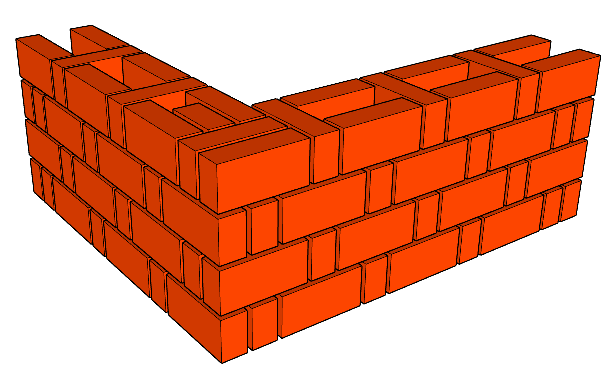
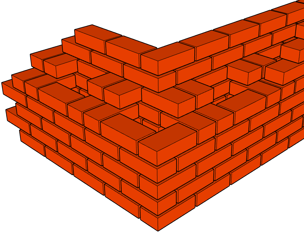
Figure 5: Rat-Trap Bond Figure 6: Spaced Double-Header
Reinforced Masonry – all types
The construction documents should identify the location of all movement joints (control joints, expansion joints, seismic joints, etc.) for structural masonry. For structural elements, this responsibility falls to the Structural Engineer of Record. It is not the responsibility of the mason to add, move, or change the location of the movement joints, as they most likely have a direct bearing on the performance of the building. Adding a joint to a wall can change the reinforcing requirements and stiffness of that one wall and the overall wall system, which may cause a redistribution of the lateral forces in the building with the potential impact of overloading some other wall or walls. Consequences may be inadequate capacity or pre-mature failure. If there is some mitigating reason to want to change the location or to add a movement joint, such changes should be vetted by the design team, and specifically the Structural Engineer of Record (SEOR).
The use of hot rolled structural steel shapes (wide flange, or “I” beams, structural steel angles, etc.) should be avoided in structural masonry wall construction, if at all possible. Introduction of non-masonry elements that serve the same purpose that can be provided by the reinforced masonry is almost always an unnecessary complication. It creates additional coordination effort and additional specialized detailing. Expansion and contraction due to changes in temperature react differently than masonry and can be a long-term maintenance problem. If structural steel elements are shown interlaced or embedded in structural masonry elements on the construction documents, it may be prudent to request a substitution to use all structural masonry elements in lieu of the structural steel. This can even extend to using structural masonry columns or pilasters in lieu of steel columns.
Masonry Veneer:
Masonry veneer can come in many unit sizes and profiles, including custom shapes, but they all must be tied back, or anchored, to some substrate wall system. These veneers are not reinforced and rely on the strength and stiffness of the substrate wall system for stability and to resist wind and seismic forces. All the forces perpendicular to the face of the wall are transferred through the ties and resisted by the substrate wall. The current code limits the deflection of the substrate wall, which generally only impacts wood stud and steel stud framed walls. Tall stories (over 12– to 15-feet) can require very large, stiff framing members.
The substrate walls intended to receive anchored veneer should comply with construction tolerances that are associated with the particular wall system, be it concrete, masonry, or wood or steel framing members. It is critical that the substrate walls be reviewed by the mason prior to the start of masonry installation to ensure that the prescriptive construction tolerances of the masonry material will work. If the substrate walls are not located correctly, or are not plumb, or are not flat, or do not form the correct intersection angle at corners, then the masonry installation may be compromised and found to be not in compliance.
For masonry veneer cavity walls, the air gap behind the veneer is limited to 1” minimum and 2” maximum in order for standard ties to work. If the air gap is less than 1”, then the installation does not meet code. If the air gap exceeds 2” then specialty ties may be required. If the ties do not extend a minimum of 1-1/2” into the bed joints of the masonry veneer, then the ties are not code compliant. If the ties extend to within 5/8” of the exterior face of the veneer, then the ties are not code compliant.
Movement Joints:
Generally, all veneers, whether concrete or clay, will require some system of movement joints: ‘control joints’ in concrete units, and ‘expansion joints’ in clay units. These joints are to be clearly shown on the construction documents. The current TMS code says, “Show or indicate … provision for dimensional changes resulting from elastic deformation, creep, shrinkage, temperature, and moisture.”
If movement joints are not clearly shown or depicted on the construction drawings, it would be prudent for the mason to issue a request for information to clarify location and size of the joints, assuming joints are required. It is not the mason’s responsibility to determine where joints are needed, or to place them somewhere other than at designated locations without prior approval. Typically, only very small buildings would not have the need for movement joints in masonry veneer. Veneer joints generally occur at intervals around 25 to 35 feet, depending on the configuration of the walls, location and frequency of building corners, locations of steps in the walls, locations of steps in the foundation, and at intersections of dissimilar framing systems, among other anomalies.
Code Changes:
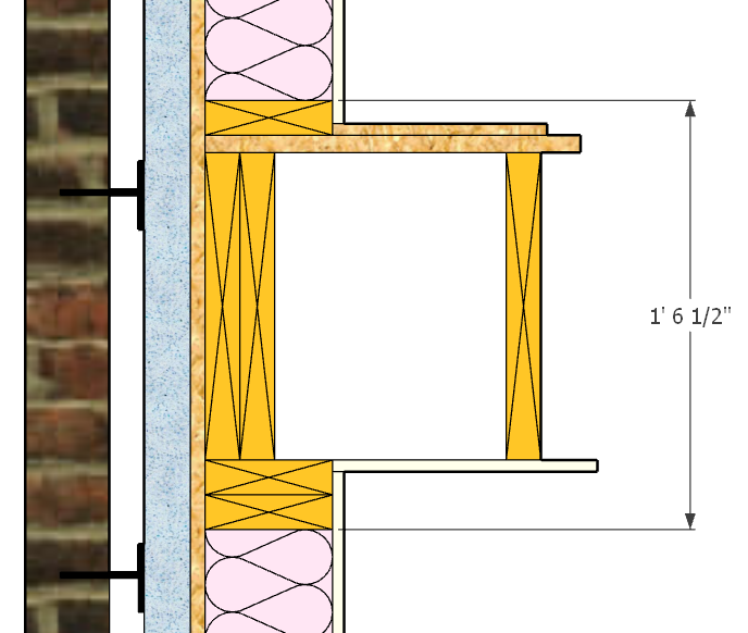
The 2022 TMS 402/602 code has many changes, revisions and additions related to anchored (and adhered) masonry veneer. One item of note is that the new edition of the code allows anchored brick veneer over “light” wood framing (wood stud framing) to exceed the prior height limit of 30 feet, or 38 feet at a gable, from the brick support. There is no height limit in the new edition of the code. There is no code requirement to provide support for the anchored veneer above that 30-foot height. The caveat is that the tie system is required to be designed and detailed to accommodate differential movement (between the veneer and the framing). For wood framed buildings utilizing platform framing techniques, there can be up to 1/4” per floor of shrinkage of the wood framing – mostly in the cross-grain direction of the top and bottom plates and the rim joists. See Figure 7.
For a six-story building with full height brick cladding, the five elevated floor assemblies can shorten the wood framing by 1-1/4” at the mid-height of the sixth floor, and the brick may expand due to moisture absorption, increasing in height approximately 1/32” per floor for an increased height of the brick over 1/8” in this scenario.
Add expansion of the brick from ambient temperature increase and from direct radiation from the sun and the veneer may increase the height of the brick at the mid-height of the sixth floor by an additional 3/16” for a total differential movement between brick and wood framing becomes 1-1/4” + 1/4” + 3/16” = 1-11/16”. Typical 2-piece adjustable ties only have the capability to accommodate half of a brick height, and so, for 2-1/4” tall (modular) brick, that would only be 1-1/8”. The movement expected exceeds the movement potential of the ties by about 1/2”.
Without the proper consideration for these movements, the ties may fail in the upper areas of the veneer – assuming the ties are placed very accurately. Any brick veneer over 40-feet tall backed by wood stud framing is suspect for differential movement challenges and the potential need for specialty ties.