Masonry Wall Flashings
Words: Dan Kamys
Moisture Management
By Douglas R. Stieve, RRC, AIA
Preventing water leakage through masonry fa??ades in contemporary construction is primarily accomplished by the use of well-placed flashings. Masonry walls, which are largely composed of brick, concrete masonry units (CMU), cast stone, and other related units, typically absorb moisture and rain. The masonry industry understands that water penetration through the outer wythe of veneers will occur. This penetration has to be managed by flashings, which divert the water back to the exterior. Water can enter the wall system at numerous locations, including individual masonry units, mortar joints, the interface between the mortar and the masonry units, at the tops of walls, at cracks, and at penetration details such as windows, doors, and pipes. The purpose of this article is to discuss the design and installation of masonry wall flashings at several typical locations throughout a building.
Wall flashings are typically required at locations where the downward flow of water inside the wall would be obstructed or interrupted. Flashings are also used under masonry copings, sills, and other horizontal surfaces. In order to understand how masonry wall flashings work, it is important to first understand the different types of masonry walls.
Load-bearing walls
Older masonry buildings were constructed with thicker, solid, load-bearing walls. Water infiltration in load-bearing walls was resisted by the mass of the multiple-wythe wall and a few well-placed flashings. Load-bearing walls performed well as long as it stopped raining before water was absorbed all the way through the mass of the wall. Flashings in these walls typically occurred at junctures of roofs and walls and at parapet locations. Often, the flashings extended completely through the wall. These flashing materials were typically made of soft metals such as copper or lead. Sometimes, masonry ledges or projecting elements (often referred to as water tables) deflected water off the fa??ade as it flowed down the face of the building.
Drainage cavity walls
Masonry veneer construction consisting of a single-wythe of brick/masonry over a back-up wall system, which gained popularity in the 1950s, is a departure from thicker load-bearing wall construction. These walls accommodate inevitable water penetration through the masonry veneer with a drainage cavity. This cavity allows water to flow down the backside of the veneer. The water is then expelled from the cavity back out of the building by the flashings. For this type of wall to function properly, the drainage cavities have to be kept clear of mortar droppings and other blockage. Since water that penetrates the masonry veneer can flow unobstructed down inside the wall, the proper installation of the flashings is more critical than in a thicker masonry wall system.
Single-wythe walls
Single-wythe masonry walls (one vertical row of masonry one unit in thickness) are predominantly constructed with CMU but can be constructed with brick. These walls do not include a drainage cavity. The cores of single-wythe CMU walls can be filled with reinforcing steel and grout. As such, they can also function as load-bearing walls. Water must be resisted at the outside face of these walls. Sometimes, water repellents and masonry sealers are used. Flashings are provided at the same locations as in veneer construction. However, single-wythe walls do not have a drainage cavity other than the inside voids in the CMU or brick. Therefore, water has many locations where it can be absorbed or can bridge across the width of the masonry veneer to the building interior.
Flashing components
In order to understand how to properly flash a masonry wall, a review of terms both commonplace and specific to vertical walls should be given consideration.
Drips
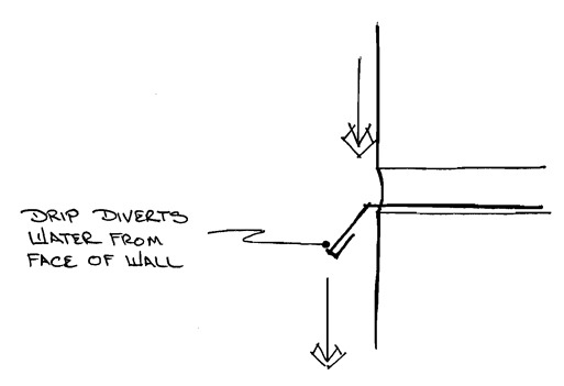
Drips are important because they divert water away from the surface of the wall (see Figure 1). These become more critical with flat wall surfaces. Older buildings used masonry components such as ledges and water tables to divert water that flowed down the surface of the building away from the exterior walls. Many times, drips are opposed by the designer for aesthetic reasons. When flashings are specified to be terminated within the face of the masonry veneer and not “daylighted” to the exterior, water may flow off of the edge of the flashing and be retained within the wall.
Weeps
The most common types of weeps are plastic tubes and prefabricated plastic or mesh materials that are placed in head joints (vertical mortar joints). Effective weeps can also be provided by leaving head joints open. However, weeps also create openings where wind-driven rain can enter the wall and thus expose the flashing to more water. The wall flashings have to be installed well to prevent potential water intrusion from creating a problem. If the wall surface will be exposed to wind-driven rain, such as at upper stories of buildings or at coastal locations, the weeps should be turned downward or otherwise baffled to prevent water from entering. Plastic weep tubes with downward curvatures can be used. Prefabricated mesh materials placed in mortar head joints in lieu of mortar look nice on paper but have limitations in the field. During construction, masons often accommodate small dimensional tolerances in the length of a wall by varying the size of head joints. Therefore, some weep systems that are prefabricated to a specific size cannot accommodate these changes in the size of head joints.
End dams
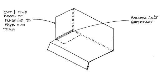
These are upturns that are constructed at the terminations of the flashing. End dams should be constructed wherever flashings terminate within a wall to prevent water from simply flowing off the side of the flashing within the masonry wall rather than being directed to weeps where it can flow out of the wall. End dams are constructed by cutting and folding the flashing material. Joints are soldered or sealed (see Figure 2).
Joints and laps
Locations where adjacent sections of flashing are joined are critical. Often, water can flow through the flashing at openings at lap joints. Laps in sheet metal should be either soldered or properly sealed, depending on the material being used.
Expansion joints in long sections of flashing are particularly susceptible to water infiltration and should be avoided whenever possible. They are usually only required at expansion or control joints in the wall and in some sheet metal flashing assemblies. If a large section of masonry is constructed on top of the flashing, the weight of the wall sitting directly on top of the flashing will resist differential movement between the metal and masonry. The usual distance between expansion joints can therefore be lengthened.
Materials
As with roofing systems, there are numerous materials that can be used to flash different components of a wall. Each has advantages and limitations, such as – but not limited to – durability, workability (ability to be formed and or soldered in the field), and cost.
Sheet metal
For centuries, sheet metal has been widely used to flash masonry walls. Lead sheets similar to roof drain flashings were formed in various shapes within the walls. Copper was also common. The author prefers metals such as copper (16 and 20 oz.), lead-coated copper (16 and 20 oz.), and stainless steel (28 and 26 ga.). These metals have unique abilities in that they can be formed and soldered in the field and will not corrode excessively under normal circumstances. These metals can be field-formed into various shapes such as inside and out-side corners, step flashings, or at unusual penetrations. Sheet metal is typically more durable than membranes and can withstand masonry being constructed directly on top of it. Environmental and potential worker safety concerns have recently limited the use of lead and lead-coated copper. Combinations of zinc and tin are being used to coat copper and other metals replacing lead. However, many of these formulated products have not yet stood the test of time, and sheet metal workers may not be familiar with how such products have to be prepared or how they behave during soldering.
Galvanized steel can be a cost-effective alternative to copper and stainless steel. However, corrosion staining will occur at locations where the galvanized coating has been cut, such as at the ends of the metal, and where the material is breached, such as by fastener penetrations. There are also different types of galvanizing with different longevity rates.
Aluminum will corrode if it is placed in contact with fresh cementitious materials such as mortar, grout, stucco, and/or concrete and it is usually not specified for this type of construction. However, under certain conditions, painted aluminum can be used. The paint will protect the metal until the mortar cures. Aluminum can still not be soldered in the field, so connections are made with rivets or screws and sealed with elastomeric sealant. Therefore, avoid aluminum in masonry construction wherever possible.
Limitations of sheet metal include the cost of the material and labor costs required to form the flashing and to construct watertight joints. Also, sheet metal is not flexible. Fishmouths often occur at top vertical edges of the metal if the substrate is not perfectly straight. Additionally, lengths of sheet metal are often limited to sections that can be placed on a truck and delivered to the project site; therefore, more joints are usually required.
Copper fabric flashing
These are composite products where thin (3-, 5-, or 7-oz) copper sheets are laminated within bituminous products, paper facers, or other proprietary fabrics. They provide many of the benefits of sheet metal as stated above. The bituminous versions can be directly adhered to a variety of substrates in compatible mastic. Joints in the material can easily be formed, lapped, and sealed in mastic. Copper fabric is also flexible enough to conform to irregular substrates.
The bituminous versions cannot be exposed to direct sunlight, so the material cannot extend past the face of the masonry and form a drip. Therefore, a separate sheet metal drip is required.
Rubberized asphalt membranes
These self-adhering “peel-and-stick” membrane sheets are usually 40 mils thick and consist of rubberized asphalt bonded to a polyethylene film. A disposable release liner is provided on the exposed portion of the rubberized asphalt and is removed just prior to adhering the membrane. These membranes are flexible and can be formed around many penetrations. Cutback mastics and asphalt-blended polyurethane liquid membranes are used to seal penetrations. Masonry and wood substrates must be primed and the material should be installed wrinkle-free. Membranes designed for use in wall systems should be specified. Membranes designed for use as waterproofing materials can have asphalts with lower softening points, and the asphalt can flow off the backing film in the hot environment within an exterior wall.
Flexible composite flashing
These are combinations of various materials and are relatively new to the market. The compositions are similar to copper fabric flashing in that they exploit the advantages of each material. Many composite flexible flashings are sold in rolls of various widths between 12 and 48 inches. Roll lengths can be up to 300 feet. The variety of dimensions allows the material to be unrolled along the length of shelf angles and other long flashings, avoiding laps and joints in the flashing materials.
One such flexible composite flashing system is a combination of a proprietary ketone ethylene ester (KEE) polymer membrane with a pressure-sensitive adhesive. The 40-mil composite membrane has a release paper and is installed in the same manner as a self-adhered flashing. Another product is a vinyl ethylene film bonded to fiberglass reinforcement. This material is most often used with separate metal drip edges and is typically loose-laid and mechanically fastened to the substrate or set in mortar joints of the backup masonry. Special tapes and mastics are used to seal terminations and penetrations.
Typical Flashing Locations
Flashings are more common in drainage cavity and single-wythe walls. However, in the author’s opinion, they can be just as important in thicker walls. The following descriptions and figures are generic in nature and should be modified and adapted for use in each particular building by a qualified design professional.
Base of walls
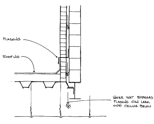
This is probably the most common location that blocks the downward flow of water within a masonry wall. Locations where rising walls are constructed directly over occupied portions of a building are particularly vulnerable to water infiltration. Any water that bypasses the flashing will very likely result in an active water leak in the occupied space below (see Figure 3). The wall cavity must not be blocked with mortar droppings, and the flashings and weeps must be very well constructed at these locations.
At the base of walls, a sheet metal flashing assembly that extends from the face of the backup wall through the masonry should be used to form a drip outside the wall. A sheet waterproofing membrane or water-resistive barrier is utilized to flash over the back leg of the metal flashing (see Figure 4). Weeps are provided through the masonry veneer. A manufactured, mortar-control device is used to catch droppings at the base of the drainage cavity so that they cannot block the weeps. The open cavity below the flashing should be filled so that there is a solid backing under the flashing at laps. This action helps prevent the bottom piece of flashing from deflecting downward as the lap seam is created.
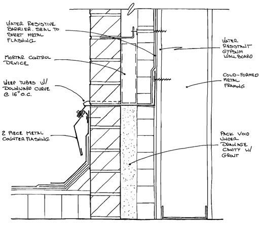 Figure 4.
There are critical components of this detail that should not be overlooked, such as lap joints, expansion joints, door thresholds, and inside and outside corners.
Shelf angles
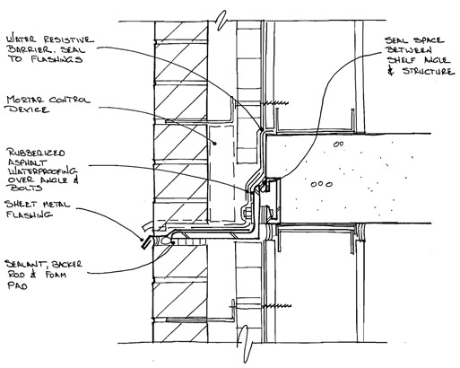
Sometimes called relieving angles, these are locations where a structural angle is provided to carry the dead load of the masonry veneer. Buildings often incorporate continuous shelf angles that support the masonry veneer at heads of windows. Shelf angles are also found at floor lines of taller buildings. These locations are similar to those at the base of a wall. However, the flashing must form around the toe of the angle. Also, if the angle spans any considerable distance, it will most likely be either welded or bolted back to the structure of the building. A flexible flashing can be formed around the bolt heads (see Figure 5).
Window and door heads
Flashings at window heads are very similar to those at shelf angles. There is usually a lintel or shelf angle that supports the masonry veneer above the window. However, the lintels are not continuous. It is therefore prudent to provide an upturned end dam at the end of the lintel. The intent of this practice is to prevent water from flowing off the end of the lintel, discharging water at the jamb of the window or door.
Window and door jambs
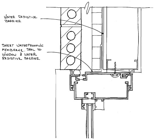
These locations, along with other penetrations through the wall such as mechanical louvers, create conditions in which water can potentially flow out of the drainage cavity migrating down the side of the window, door, or both, creating a leak. Sheet metal or flexible adhesive membranes can be used to create a dam to prevent water from flowing out of the drainage cavity and into voids at window and door jambs (see Figure 6).
Window sills and door thresholds
Locations below windows and doors – particularly at areas directly below the jambs – are vulnerable to water infiltration. These are locations where individual framing members of windows and doors intersect at an opening in the masonry veneer. Flashings at these locations should have an upturned back leg to prevent water from flowing off the back of the flashing. An end dam should also be provided to prevent water from flowing off the side of the flashing. If the window or door is near the base of the wall, the flashing should form a continuous envelope and be connected to the adjacent wall flashing.
Masonry copings
Copings constructed with stone, precast concrete, or masonry should not be considered watertight. Water can penetrate through transverse joints in the copings or be adsorbed directly through the coping unit. Parapets are subject to increased vulnerability from freeze-thaw distress because they are exposed to the elements on three sides. A flashing should be provided directly under the coping to block water from flowing down through the wall. Dowels or other types of coping anchor penetrations through the flashings must be sealed (see Figure 7).

Workmanship
Although masonry flashings can prevent water infiltration into buildings at certain locations, the overall workmanship of the mason has a large impact. One of the most common workmanship problems is mortar that falls down the inside of the drainage cavity. The mortar can harden and block the flow of water out of the weeps. Mortar droppings can also collect on wall ties and provide locations where water can bridge across the drainage cavity. Drainage composite materials are available. These mesh-like materials are placed at the bot-cavity, it will cover the top of the drainage composite.
Conclusion
Flashings are a critical component to the overall water management performance of masonry wall systems. All parties, including the owner, designer, general contractor or construction manager, and sub-contractors, must be aware of the critical nature of these flashings. During the inevitable value-engineering process, modifications are often made that can either eliminate some of these flashing components or substitute materials that may not perform as well as originally intended. Designers must be knowledgeable enough to educate the owner as to the advantages and disadvantages of these proposed substitutions. There is also a coordination burden placed on the general contractor and/or construction manager and various subcontractors, as more and more portions of the exterior building envelope are constructed by different entities.
Reprinted with permission from the August 2007 issue of RCI’s Interface technical journal.?? RCI is an international association of building envelope consultants. Its members specialize in design, investigation, repair, and management of roofing, exterior wall, and waterproofing systems. The association’s 2,600 members are found throughout the United States and Canada.?? Educational programs, professional registrations, and technical publications are primary products of RCI.
RCI members are recognized for their professional expertise and adherence to an ethics code that offers consumers assurance of unbiased, objective consulting service. The associations’ professional registrations: Registered Roof Consultant (RRC), Registered Roof Observer (RRO) and Registered Waterproofing Consultant (RWC), Registered Exterior Wall Consultant (REWC), and Registered Building Envelope Consultant (RBEC) are preferred standards for those of the consulting profession.??For more information, visit www.rci-online.org.
Return to Table of Contents