Marvelous Masonry- Celebrating Masonry's Heritage: Nepal
Words: David Biggs, Andres ArceWords and Figures:
David Biggs, US-based consultant and regular columnist for Masonry (Marvelous Masonry series) and Masonry Design (Technical Talk) magazines
Andres Arce, Consulting Heritage Engineer currently completing his PhD at the University of Patras, Greece
BACKGROUND
Nepal is known for being home to the highest peaks in the world. Situated between the boundary of the Indian Plate and the Tibetan plate, Nepal’s magnificent mountains have developed due to the tectonic activity that results in devastating earthquakes nearly every 75 years. Despite the high seismicity, many Nepal buildings were not built to resist earthquakes. Historical records show a great deal of loss of human life and damage to infrastructure following each large magnitude earthquake. One such earthquake occurred on April 25, 2015 (2015 Gorka Earthquake) near the capital city Kathmandu with a magnitude of 7.8. That earthquake had over 470 aftershocks of magnitude four or greater, with the largest being 7.3 on May 12. The death toll exceeded 9,000, with over 22,000 additional injured and over 600,000 structures damaged, many masonries.
Nepal also has some marvelous masonry! Of particular interest for the authors was the Temple of Gopinath in Hanuman Dhoka, a complex of historical structures in Durbar Square, Kathmandu, located as shown in Figure 1. The authors had the opportunity to visit the temple at separate times, David while working on a post-earthquake humanitarian mission in 2015, and Andres while working as a structural engineer on a United Nations (UNESCO) team designing the repair-retrofit of the temple in 2017 with David assisting. The authors have worked together on other projects since 2010 in Costa Rica and Italy.
 Figure 1. Location of Gopinath Temple in Hanuman Dhoka Durbar Square, Kathmandu Valley, Nepal
The Gopinath Temple (Figure 2), was donated by a royal patron to be a state temple. Based on a study of the details and stylistics of the carved elements, it is believed the temple was built c. 1641 CE - 1674 CE.
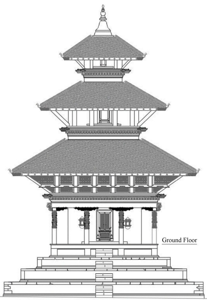 Figure 2. Elevation view of the Gopinath Temple
The three-tiered pagoda-style temple is dedicated to the god Vishnu and has a square floor plan mounted on a four-step plinth. The three roofs are supported by highly decorated wooden struts depicting the various incarnations of Lord Vishnu and Salabhanjika. The artisanship in these carvings makes these struts some of the finest examples from the late Malla period.
DESCRIPTION OF EXISTING STRUCTURE
The structural system of the 36-foot-high temple (Figure 3) is typical of most Nepal temples with a box-type configuration of unreinforced load-bearing brick masonry walls and timber framing. The brick masonry was built using yellow mud as the mortar. The timber (mainly Sal wood) was used ornamentally and as structural elements such as beams, wall-plates, rafters, columns, and links between masonry walls. The roof has timber planks covered with mud and protected by a layer of tiles. Looking at Figure 3, the temple has thick bearing walls continuously from the ground to the third level. At the ground floor level, the walls have one opening on each face and are surrounded by a colonnade of timber columns supporting 8” x 10” timber beams. Those beams support 15-inch-thick secondary masonry walls that occur only between the first and second levels. The third-level masonry walls are offset from the main load bearing walls and are supported by 9” x 6” timber beams.
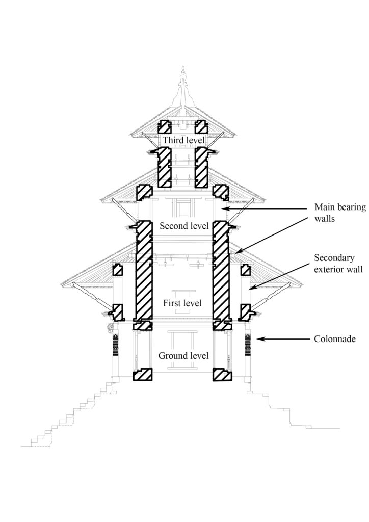 Figure 3. Cross-section of the temple structure with masonry walls highlighted
PLINTH
Nearly 10-feet high, the plinth is 33 feet wide at the base and has four levels with a staircase on the east side (Figure 4). The temple’s colonnade has a plan dimension of approximately 19 feet.
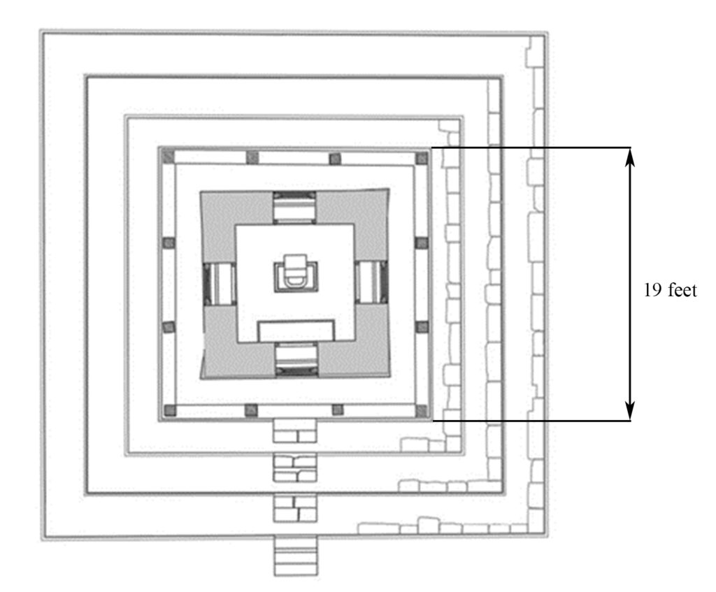 Figure 4. Plan view of Plinth and ground floor level of the Gopinath Temple
FOUNDATIONS
Most conservation works in Nepali architecture are done on the plinth upwards; therefore, little is known about the foundation of Nepali temples. It has been suggested that a foundation wall runs down to the bottom of the plinth and that the depth of the foundation of tiered temples varies from 3 to 10 feet. Sjoerd (2003) described a configuration of the foundation walls (Figure 5). A photograph of the brick foundation exposed after excavation is shown (Figure 6). Excavations in 2016 indicated the 2015 earthquake had not damaged the foundations.
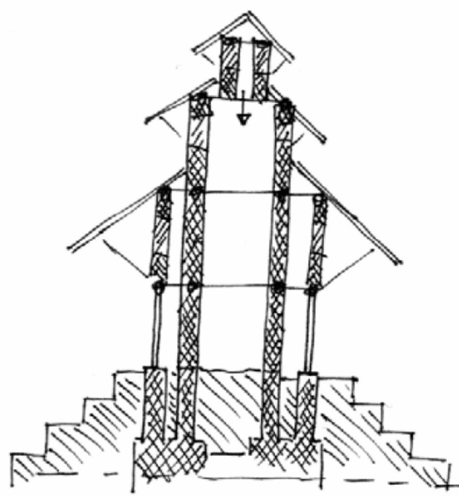 Figure 5. Foundation system according to KVPT (Sjoerd, 2003)
 Figure 6. South facing elevation of the brick foundation (Coningham, et al., 2017)
MASONRY WALLS
The main brick bearing walls are at 29 inches at ground level and diminish to 27 inches, 25 inches, and 20 inches, respectively, for the first, second, and third levels. They are made of two classes of brick, a finishing brick for the exposed exterior faces called Dachi Appa, and a structural brick called Ma Appa. Nepal bricks are generally hand-molded.
Figure 7 shows a portion of the interior face of the Ma Appa bricks with mortar, while Figure 8 shows Dachi Appa bricks used on the exterior with no exposed mortar (also see Figure 10). The Dachi Appa units are a unique element of Nepali traditional architecture; they are asymmetrical, as seen in Figure 9; notice the trapezoidal shape; the geometrical intention is to reduce the size of the exposed joint to protect the mortar and increase durability.
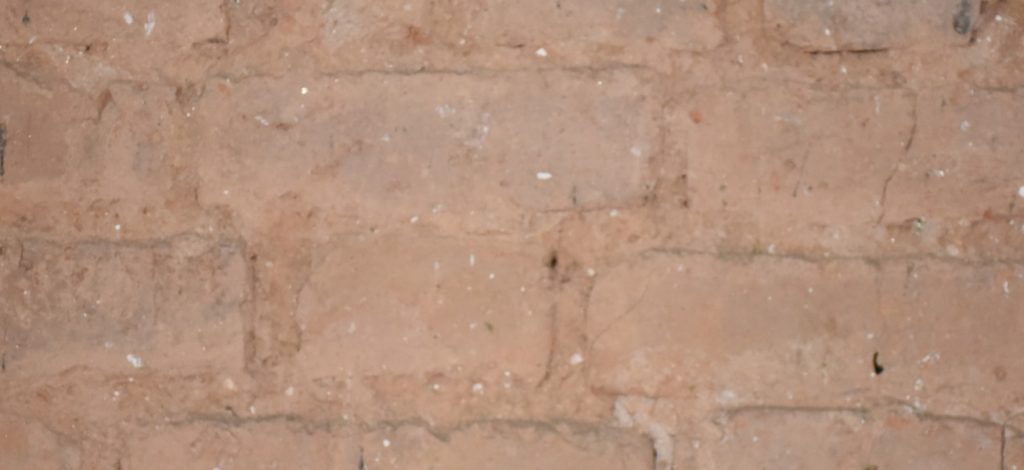 Figure 7. Example of masonry at the interior of the temple. Ma Appa bricks.
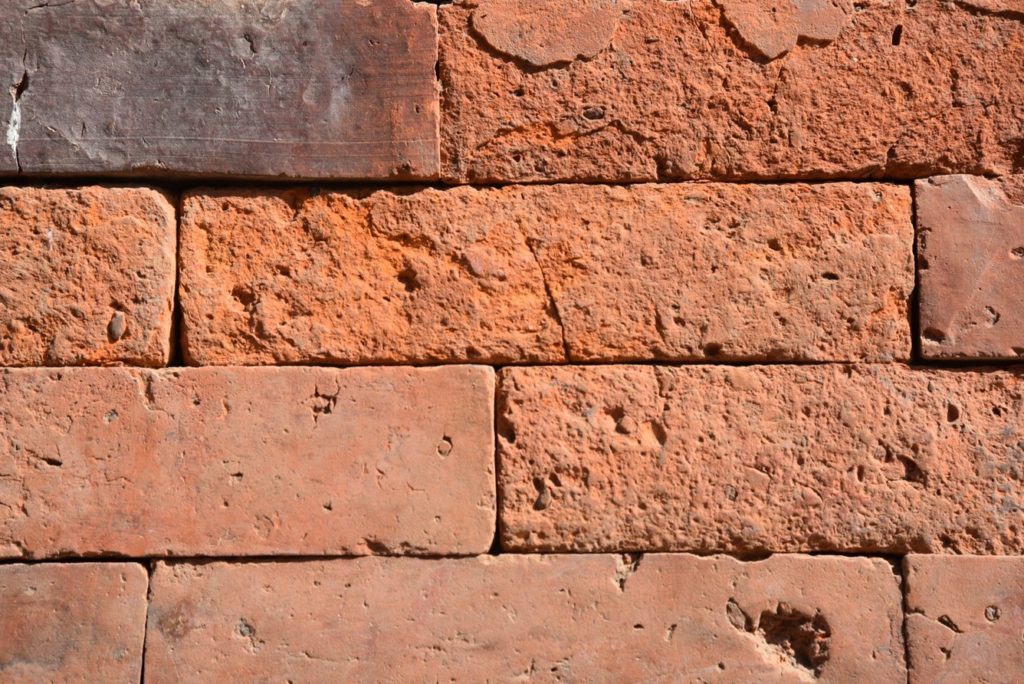 Figure 8. Example of masonry at the exterior walls using Dachi Appa bricks.
 Figure 9. Dachi Appa Bricks showing the unsymmetrical shape
Figure 10 shows how Ma Appa and Dachi Appa bricks are combined to make walls in Nepali architecture, the Dachi Appa brick commonly of higher quality is used for the finished exterior layer that is exposed to more deterioration.
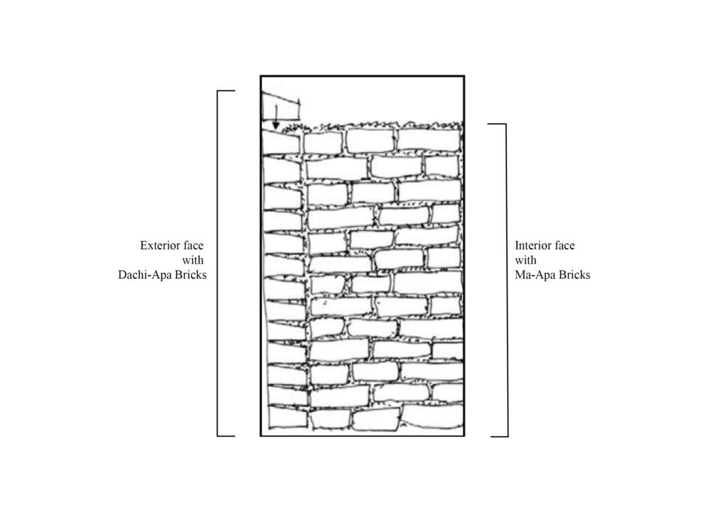 Figure 10. Cross-section of ground floor level masonry wall
 ROOF SYSTEM
The Nepali temple architecture is represented by elaborate wooden roofs of timber elements and clay tiles. Traditionally clay tiles are laid over a layer of mud. This mud layer can vary from 6 inches at the top to 3/4 inches at the eaves.
Connections between the roof and brick walls are achieved through wooden pegs (see Figure 11 – arrow at the first level). One connection limitation is the concentration of stresses produced in the contact area peg-to-masonry during seismic events. During the recent earthquake, some wooden pegs were deformed or broken, while some of the bricks in contact with the pegs broke.
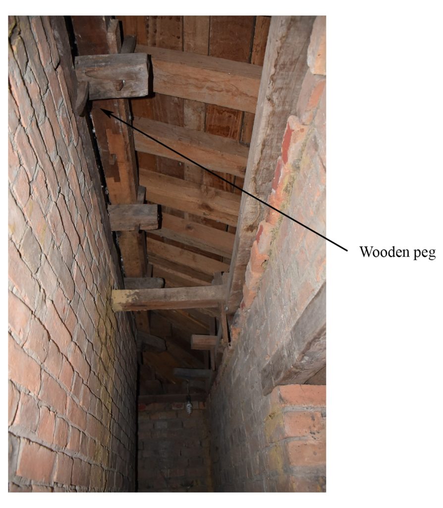 Figure 11. Photograph of roof section between the bearing wall of left and outer over the colonnade wall on the right (also see Figure 3)
Figure 12 shows the roof over the colonnade at the first level. The decorative lattice was added in the 2003-2004 restoration. The roof extends beyond the wall limit and protects the masonry walls. This is typical of Nepali architecture and related to using mud mortar in these structures. Since mud mortar can be washed away by water, the ancient architects designed these extensive roofs to protect the masonry walls from deterioration.
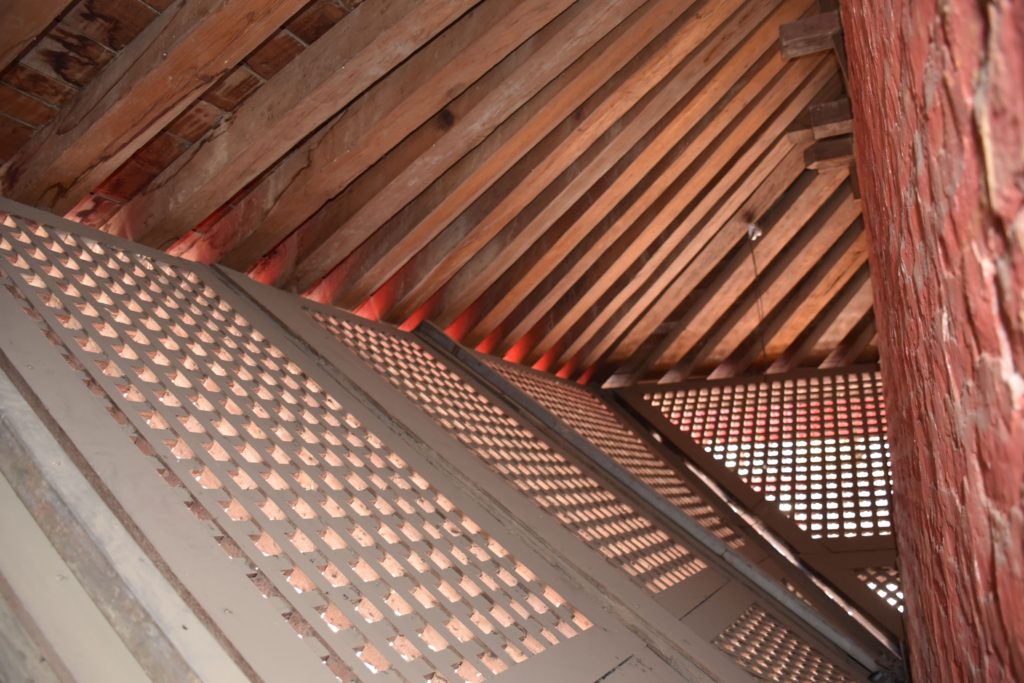 Figure 12. Roof system outside of the exterior wall
TIMBER ELEMENTS
Timber is widely used in Nepal temples to create decorative elements and provide structure. Traditionally, timber connections have no nails; they are made by carving the timber into functional shapes. Figure 13 shows an example of a column connected to a capital followed by a connection to a beam. The floor diaphragms are timber beams running west-east such that the diaphragm action only exists in one direction.
The brick walls are traditionally constructed or retrofitted with timber bands inside and outside at different levels. The bands work with the masonry to provide added strength in-plane and out-of-plane. These bands also improve the box-like behavior of the structure. They are usually 2-inches deep, so they can easily be inserted into a single course of bricks. An example of their use in the Gopinath Temple is shown in Figure 14.
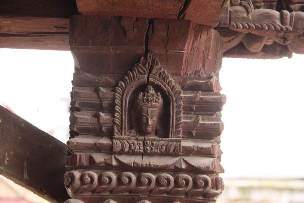 Figure 13. Corner beam column connection
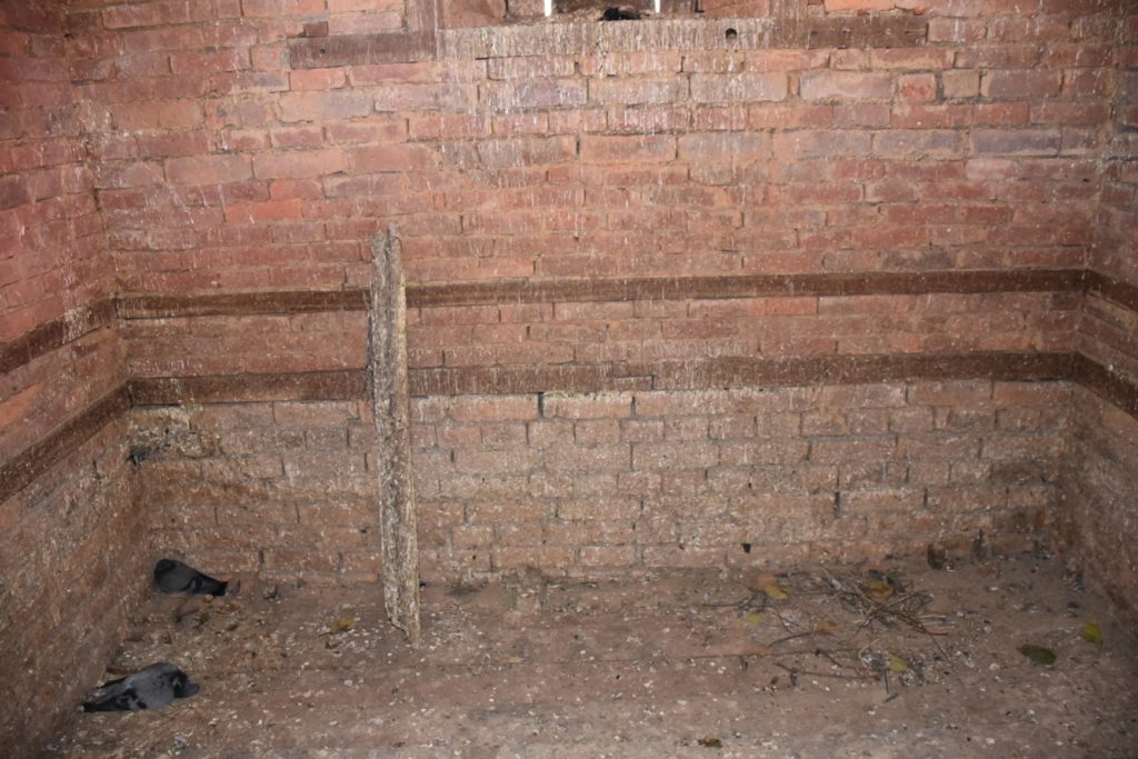 Figure 14. Timber bands embedded in masonry at first floor level
Historical Interventions
1936 INTERVENTION
The first recorded intervention to the temple dates to 1936, after the devastating 8.4 magnitude earthquake that collapsed the entire temple down to the plinth (see box - Figure 15). It is believed that due to the urgency of repair and lack of resources, the temple was quickly rebuilt (Figure 16) without enough attention to its previous historical configuration. The ground-level walls were reconstructed using lime mortar, while yellow mud mortar was used above.
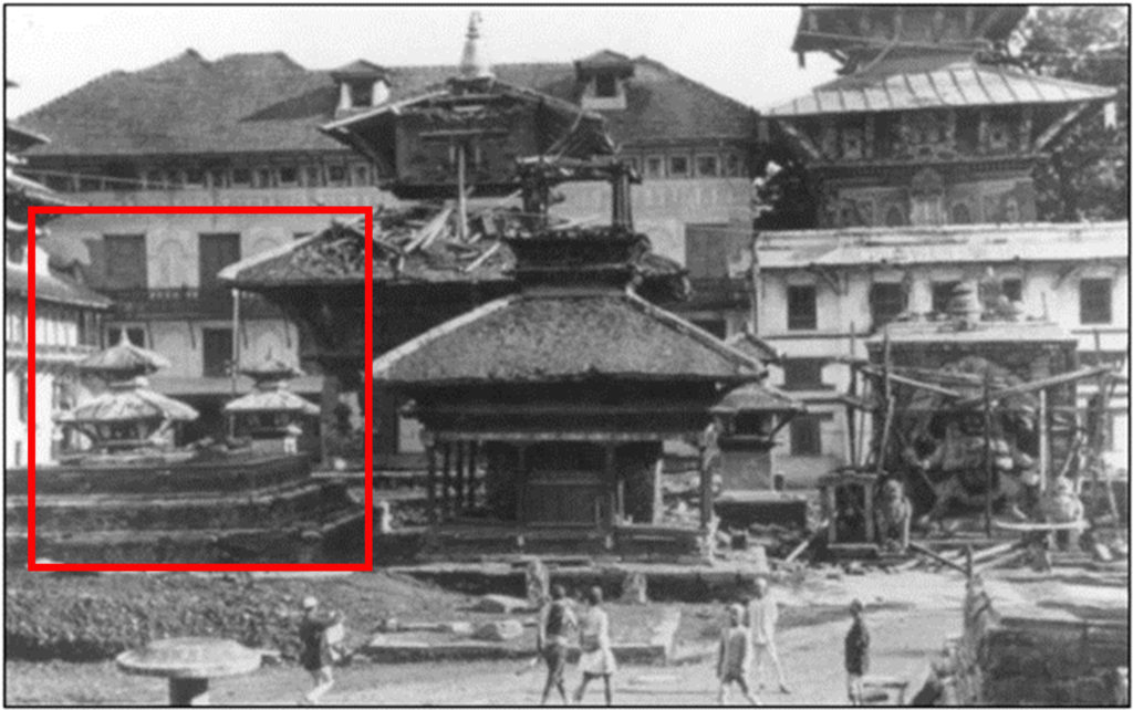 Figure 15. Complete collapse after the Bihar earthquake 1934. Source: Manju Rana
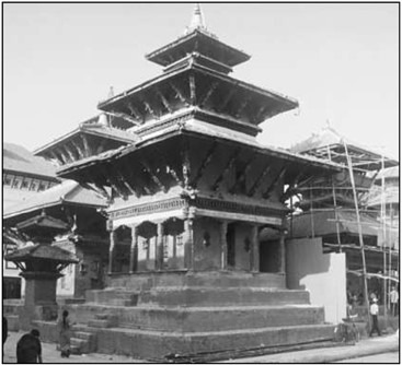 Figure 16. Gopinath temple after 1936 reconstruction. Source: Raju Roka, September 2002
2004 INTERVENTION
The previous foundation had developed gaps. A soil layer was removed and refilled with rubble masonry.
The exterior layer of 1936 bricks was replaced with Dachi Appa using yellow mud mortar. The interlocking between the new layer of bricks and the old one was achieved by introducing copper rods every three bricks and using new interlocking bricks.
The masonry walls at the first level were reported to be in good condition, likely due to the use of lime mortar in 1936. No interventions were reported for this level. At the second level, the masonry walls were dismantled to replace the masonry works from the 1936 restoration. The reconstruction material was Dachi Appa bricks set in yellow mud mortar. New timber wall plates, like ring beams, were reinforced with steel plates. Figure 17 shows part of the reconstruction work.
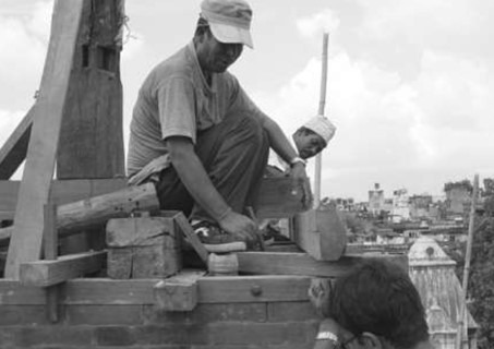 Figure 17. Carpenters fitting the wall plates incorporating steel plates.
Credit: Badri Juwal, 2003Deterioration made it necessary to dismantle and reconstruct the lower roof with new timber. A waterproofing membrane was added to prevent future water-related damage. For the middle and upper roofs, damaged wood in the carved struts was carefully cut out and replaced. Figure 18 shows the temple after its second documented intervention.
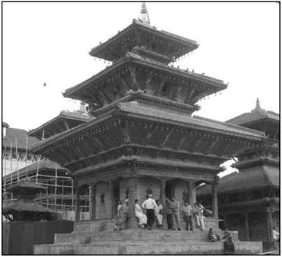 Figure 18. Gopinath temple after 2004 reconstruction. Source: Raju Roka, April 2004
DAMAGE ASSESSMENT AFTER THE 2015 EARTHQUAKE
The structure suffered extensive damage to the unreinforced brick masonry walls on the ground-floor and first-floor levels. The highlights of the damage in 2017 are:
Heavy damage is seen in Figure 19. Slender timber elements were used as temporary façade shoring, preventing the full delamination of the Dachi Appa brick from the Ma Appa brick substrate.
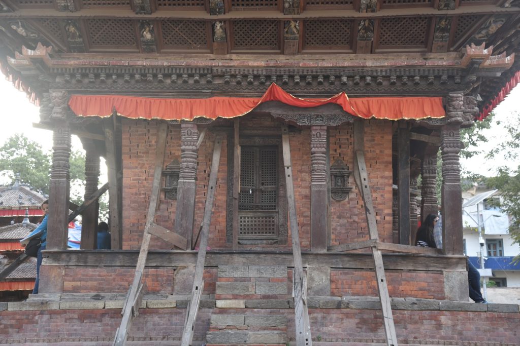 Figure 19. Gopinath Temple ground level façade with temporary façade shoring
The ground-floor level had important cracks throughout the whole width of the well (see Figures 20a and b, and Figure 21). While the Ma Appa lime masonry suffered extensive damage, the structure managed to survive the earthquake. The decision to replace yellow mud mortar with lime mortar in the 1936 intervention is the likely reason that the temple did not collapse as it did in 1934.
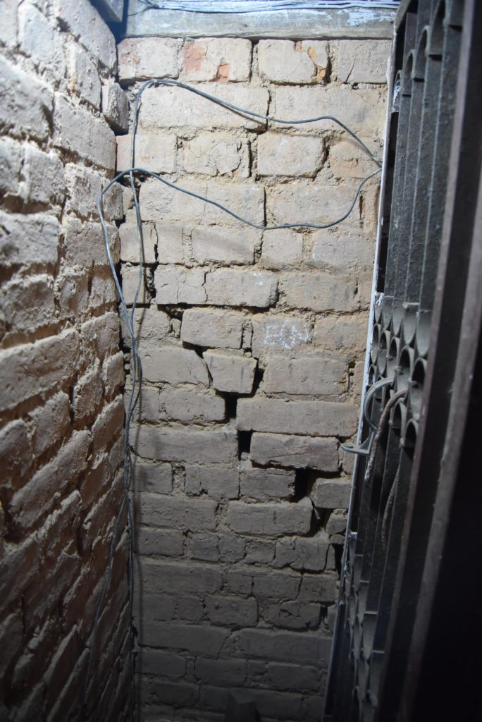 Figure 21. Shear crack observed from the interior wall in the ground level
 As mentioned, the external Dachi Appa layer was prevented from delaminating during aftershocks by immediately installing slender timber struts (more detail in Figure 22) and vertical timbers. A close-up of the displacement can seen in Figure 23 as well as the lack of mortar in between the Dachi Appa bricks.
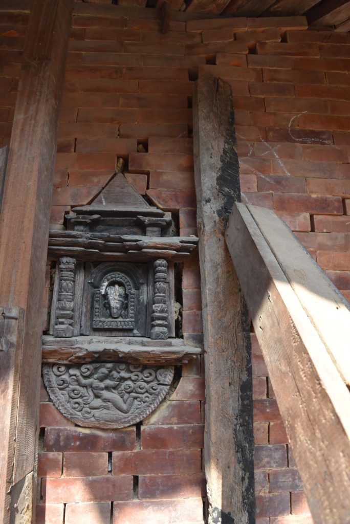 Figure 22. Temporary shoring preventing further out of plane displacement of Dachi Appa layer at the ground level
 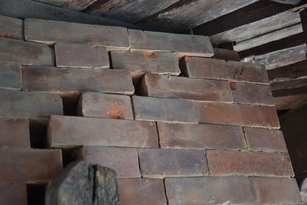 Figure 23. Out-of-plane damage close up at the upper right corner of the ground level façade wall
Another characteristic damage observed was the crushing of bricks in high compressive stress zones as the corners of openings. Figure 24 shows one example where a pair of bricks are crushed at the lower corner of a door opening on the ground level. Crushing was also observed in other high-stress areas, such as the contact zone between peg connectors and masonry, as depicted in Figure 25.
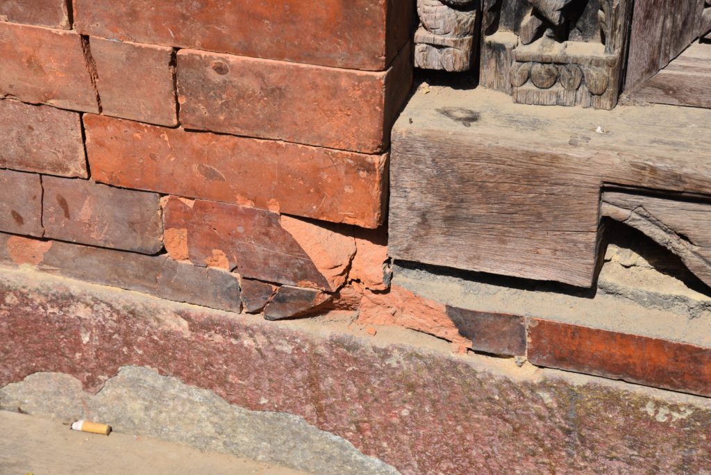 Figure 24. Brick crushing at lower left corner of door opening at ground level
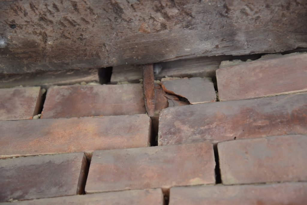 Figure 25. Brick crushing due at the contact point with timber peg connector in the ground level
Timber columns suffered vertical cracks and in-axis rotation (Figure 26).
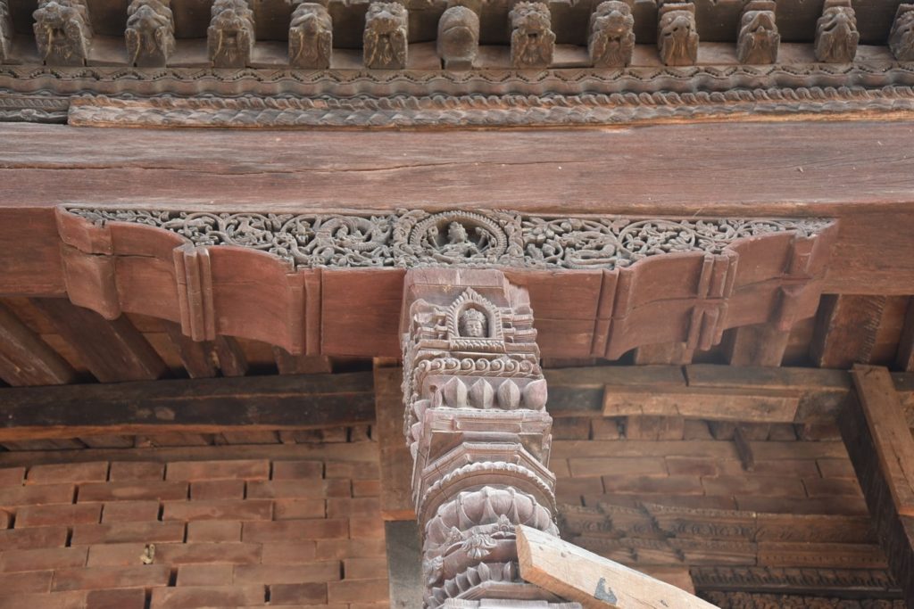 Figure 26. In-axis rotation of column and capital at the ground level
The majority of the remaining damage was found concentrated on the first level leaving the upper floors almost untouched. The first-level interior masonry walls had large shear cracks (Figure 27). The exterior wall at this level was permanently deformed in the direction outside of the wall (out of plane damage, see Figure 28).
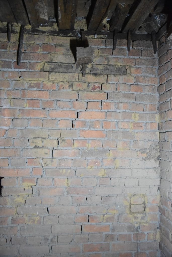 Figure 27. Diagonal shear crack observed from the inside at the first level of Gopinath Temple
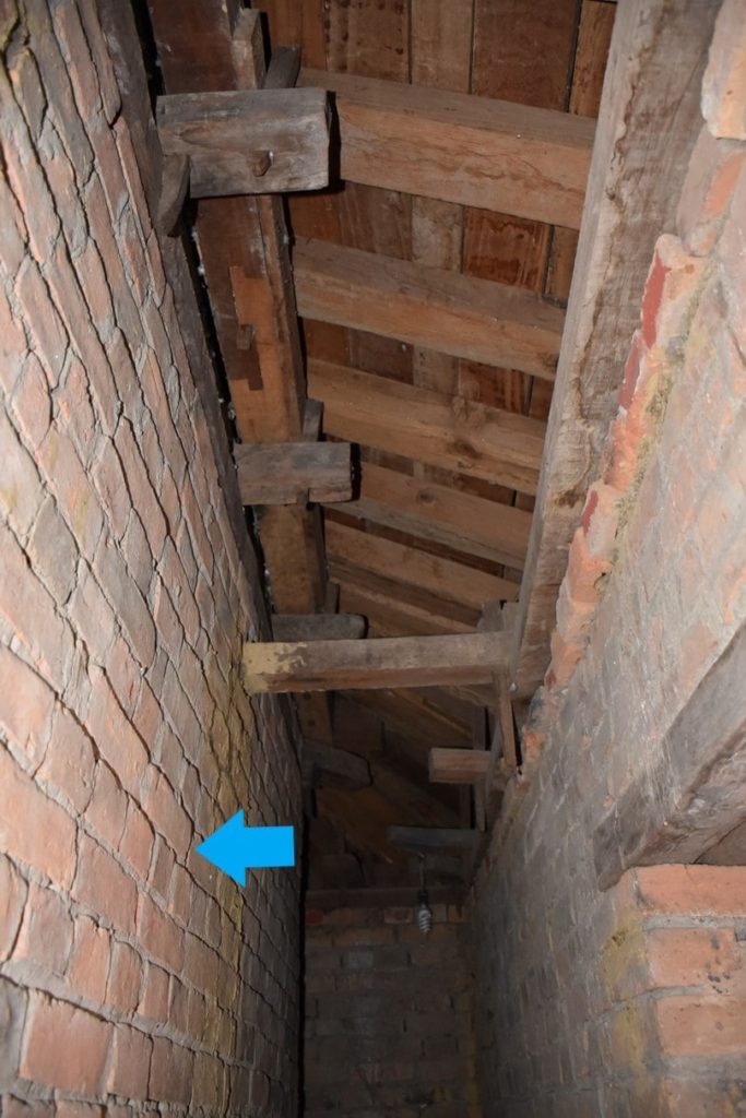 Figure 28. Out of plane deformation of the interior first-level wall
Signs indicate this wall has been repaired in the past. The mortar color of the upper brick courses is different compared to the rest of the wall suggesting previous reconstruction (Figure 29).
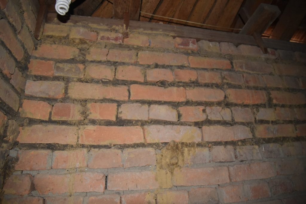 Figure 29. Different mortar on top of exterior wall
RETROFIT PROPOSAL
The ideal solution for any retrofit would be to include traditional Nepali details. One method mentioned for reinforcing masonry structures is by adding timber bands. While adding timber bands is meant to increase the wall shear capacity, they will also increase the out-of-plane capacity. Due to some previous connection failures of the timber connections, a series of tests were performed, which led to slight but significant modifications that kept the appearance similar but will improve the performance. This is a good compromise for performance improvement versus maintaining traditional joinery.
The box behavior of the masonry structure of the temple will also be improved by installing 2-inch thick timber plank diaphragms on the first and second floors. These floors are the most vulnerable due to high shear forces during earthquakes. Crushed bricks will be replaced and re-anchored. Brick crushing at the contact area of the timber pegs and masonry will be controlled by installing more pegs, thereby reducing the load on each connector. Figure 30 describes the intervention proposal.
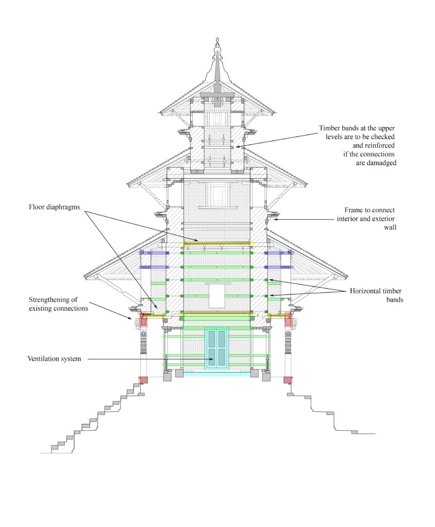 Figure 30. Proposed retrofit areas
SUMMARY
While the proposed solutions will significantly increase the seismic capacity of the temple, it is important to remember that there are multiple answers to the challenge of conserving a heritage building. Fundamentally, planning an intervention is a multi-disciplinary effort. In Nepal, that involves the participation of community leaders, priests (in the case of religious heritage), engineers, architects, historians, and government officials, making it a real challenge to come up with a satisfy-all solution.
In 2019 UNESCO withdrew from the restoration of the Gopinath Temple in the Kathmandu Valley World Heritage Site. In December 2018, the UN body had started restoration works in close partnership with Nepal’s Department of Archeology (DOA). On December 23rd, the work was placed on hold due to pressure from the locals who wished the temple be restored using local funds alone and no international assistance. A series of meetings arranged by UNESCO with local community members, The Ministry of Culture Tourism and Civil Aviation, Nepal Reconstruction Authority, Nepal’s Department of Archeology, and Parliament member, Rajesh Shakya allowed the intervention works to resume on May 15th, 2019. Days later, threats made by locals to the restoration workers forced UNESCO to shut down reconstruction works and close the project. All documentation was handed over to Nepal’s DOA.
The Nepali government is now in charge of executing the repair works in the temple. The repair works on the many monuments that belong to the Kathmandu Valley World Heritage site, including the Gopinath Temple, are ongoing. The authors collaborated in the design of the retrofit proposal that was delivered to the Nepali government, and hope the contribution has in some way facilitated the path towards the recovery of the wonderful Nepali masonry heritage.