Bonding with Masonry 2024 Q1
Words: David BiggsThis issue’s questions come from an Architect and a Mason Contractor. What questions do you have? Send them to info@masonrymagazine.com, attention Technical Talk.
Q. An Architect asks if it is necessary to specify Type M mortar for veneers that extend below grade. They had a set of drawings peer-reviewed, and the reviewer stated they should change their specifications from Type N to Type M when the veneer extends below grade.
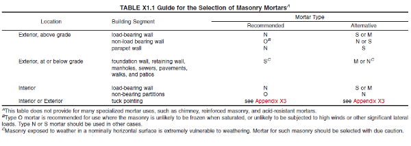
A. Thank you for the question. The authority on this topic is ASTM C270, Standard Specification for Mortar for Unit Masonry. Table X1.1 within Appendix X1.1, Guide for the Selection of Masonry Mortars recommends Type S mortar for below-grade foundation walls. (Veneers below grade become part of the foundation.) Table X1.1 also lists Type M and Type N mortars as alternate recommendations for below-grade use. So, your Type N mortar would appear adequate. However, every project should be evaluated separately based on the potential for freeze-thaw damage. Does your project have free-draining material that does not keep the veneer in a saturated condition? Is your site in a northern zone where the ground freezes for prolonged periods? For these conditions, you may want to specify a Type S or Type M unless you have a history of good performance of Type N mortar below grade.
Summary:
- The selection of mortar type for below-grade applications for veneers depends on freeze-thaw conditions and local practice.
- Type S mortar is the recommended mortar type for below-grade applications if conditions are unknown.
Q. A Mason Contractor asks about movement joints in parapets that are constructed of a reinforced CMU wall with a clay brick veneer (see Figure 1 as an example). He states that they have seen 1) closely spaced joints (approximately 6 feet on center), 2) joints spaced about 24 feet on center, and 3) 24 ft. joints in the brick but no joints in the CMU with horizontal joint reinforcement at 8 inches on center. Why are there so many variations?
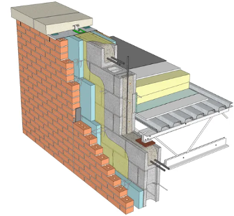 Figure 1 – Parapet (courtesy of IMI Sketchup Warehouse)
A. Your question highlights an interesting point in that there are always different design options, and this also applies to parapet design. Let’s discuss the three options you mentioned. For each option, we need to evaluate the clay brick and the CMU effects separately.
Option 1 - Closely spaced joints in both the clay brick and CMU
a. For the clay brick, we turn to BIA Technical Note 18A as the reference on joints. Brick joints are primarily intended to accommodate thermal expansion; therefore, movement joints in clay brick are often referred to as expansion joints.
The technical note provides the following formula for the recommended maximum joint spacing: Se = wj ej / 0.09
where: Se = spacing between expansion joints, in.
wj = width of expansion joint, typically the mortar joint width, in.
ej = percent compressibility of expansion joint material (least of sealant, backer, and filler)
As an example, if the joint width is 3/8 inches and the sealant is 50% compressible, Se = (3/8)(50)/0.09 = 208.3 inches = 17’-4”. Therefore, the brick joints could be spaced so they do not exceed 17’-4”.
b. For the CMU, there are several methods using NCMA Tek Notes that we have discussed in previous articles. While we are concerned with expansion for clay brick, we are primarily concerned with the shrinkage of CMU. Using TEK 10-02D, CONTROL JOINTS FOR CONCRETE MASONRY WALLS—EMPIRICAL METHOD, the maximum joint spacing is governed by Table 1 which limits the spacing to 1.5 times the height or 25 ft. maximum.
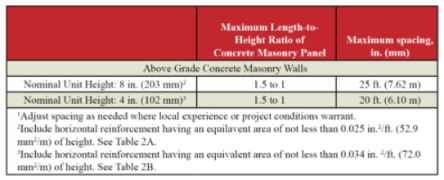 Table 1 – NCMA TEK 10-02D (Courtesy of Concrete Masonry and Hardscape Association)
For example, a partially-grouted 8 in. CMU parapet that is 3”-4” high would require joints at 1.5( 3.33) = 5.0 ft. The CMU requires horizontal joint reinforcement at 16” on center.
c. Combining the results for clay brick and CMU, an architect or engineer could use the spacing derived for the CMU to align the joints in the clay brick and CMU at 4’-8” to remain in modular spacing. The brick joints are 3/8” wide and the sealant must be 50% compressible.
Option 2 - Joints spaced about 24 feet on center
a. For the clay brick joints to be placed at about 24 feet, we need to solve the spacing formula. Se = wj ej / 0.09 = 24 x12 = 288 inches. Increasing the joint width to ½ inches would require ej = 288 x 0.09 /(0.5) = 51.8%. Therefore, if the joints are ½” wide and the compressibility of the sealant exceeds 51.8%, the joint spacing can be 24 feet on center.
b. To achieve a joint spacing of 24 feet for the CMU, we must use NCMA TEK 10-03, CONTROL JOINTS FOR CONCRETE MASONRY WALLS – ALTERNATIVE ENGINEERED METHOD.
Note 2. of Table 1 of TEK 10-03 allows the designer to ignore the panel size of the parapet panel by increasing the horizontal reinforcement. Specifically, the reinforcement must exceed 0.002 times the net cross-sectional area of the masonry. Table 3 of the TEK note provides reinforcement options.
For the same partially-grouted 8 in. parapet from Option 1, 2-#4 bars in the top course as seen in Figure 1 and one additional bond beam with a #4 horizontal bar would satisfy needed reinforcement. Any movement joint spacing would be acceptable.
c. Combining the clay brick and CMU results for this option, an architect or engineer could use the spacing derived for the clay brick to align the joints in the clay brick and CMU at 24’-0” to remain in modular spacing. The brick joints are ½” wide and the sealant compressibility must exceed 51.8% (usually 75% is used).
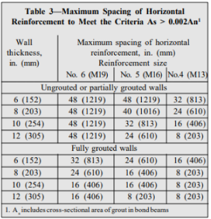 Table 3 – NCMA TEK 10-03 (Courtesy of Concrete Masonry and Hardscape Association)
Option 3 - 24 ft. joints in the brick but no joints in the CMU with horizontal joint reinforcement at 8 inches on center
a. From Option 2, we determined the joint width and sealant to achieve a 24 ft clay brick joint spacing.
b. From Option 2, we also determined the amount of horizontal reinforcement that must be used in the parapet to eliminate movement joints. Note: From Table 3, horizontal joint reinforcement at 8 inches on center would not provide sufficient reinforcement; bars must be used.
c. Combining the clay brick and CMU results for this option, an architect or engineer could use the spacing derived for the clay brick. The brick joints are ½” wide and the sealant compressibility must exceed 51.8% (usually 75% is used). No joints would be required for the CMU. Caution, even though no movement joints are required in the CMU, designers should still provide joints near corners.
Summary:
- Quite often for masonry design, there are several options that give differing results. This is illustrated with the design of parapet jointing where there are different standards.
- Expansion joint spacing for clay brick is controlled by the width of the joints and the compressibility of the material (sealant, backer rod, and filler) placed in the joint.
- Placing horizontal joint reinforcement at 8 in. on center in the parapet does not provide the necessary amount of reinforcement to eliminate or greatly expand joint spacing; reinforcement bars are required.
Thank you again for following this column. Remember, by bonding, we get stronger! Keep the questions coming. Send them and your comments to info@masonrymagazine.com, with attention to Technical Talk. If you’ve missed any of the previous articles, you can find them online for Technical Talk, Bonding with Masonry at Masonry Design
(https://www.masonrydesignmagazine.com/?s=biggs).
David is a PE and SE with Biggs Consulting Engineering, Saratoga Springs, NY, USA (www.biggsconsulting.net), and an Honorary Associate Professor with the University of Auckland, NZ. He specializes in masonry design, historic preservation, forensic evaluations, and masonry product development.
Keywords for this issue: below-grade mortar, veneer, movement joints, expansion joints, parapets